ENGINE ASSEMBLY REMOVAL

CAUTION / NOTICE / HINT
CAUTION:
The engine assembly with transaxle is very heavy. Be sure to follow the procedure described in the repair manual, or the engine lifter may suddenly drop.
PROCEDURE
-
PRECAUTION
Note
After turning the ignition switch off, waiting time may be required before disconnecting the cable from the negative (-) battery terminal. Therefore, make sure to read the disconnecting the cable from the negative (-) battery terminal notices before proceeding with work.
-
RECOVER REFRIGERANT FROM REFRIGERATION SYSTEM
-
DISCONNECT CABLE FROM NEGATIVE BATTERY TERMINAL
Note
When disconnecting the cable, some systems need to be initialized after the cable is reconnected.
-
PLACE FRONT WHEELS FACING STRAIGHT AHEAD
-
REMOVE FRONT WHEELS
-
REMOVE OUTER COWL TOP PANEL
-
REMOVE NO. 1 ENGINE COVER
-
Hold the rear of the No. 1 engine cover and slowly raise it to detach the clip on the rear side.
-
Raise the cover to detach the 3 clips on the front side and remove the No. 1 engine cover.
Note
Attempting to disengage both front and rear retainers at the same time may cause the No. 1 engine cover to break.
-
-
REMOVE NO. 2 RADIATOR AIR GUIDE
-
Remove the 7 clips and No. 2 radiator air guide.
-
-
REMOVE FRONT BUMPER ABSORBER LOWER
-
Remove the 8 bolts, 4 screws and front lower bumper absorber.
-
-
REMOVE NO. 1 ENGINE UNDER COVER
-
Remove the 11 clips, 6 bolts and No. 1 engine under cover.
-
-
REMOVE CENTER NO. 4 ENGINE UNDER COVER (w/ Cover)
-
Remove the 2 clips and center No. 4 engine under cover.
-
-
REMOVE FRONT NO. 3 ENGINE UNDER COVER
-
REMOVE REAR ENGINE UNDER COVER LH
-
Remove the 5 clips and rear engine under cover LH.
-
-
REMOVE REAR ENGINE UNDER COVER RH
-
Remove the 5 clips and rear engine under cover RH.
-
-
DRAIN ENGINE COOLANT
-
DRAIN ENGINE OIL
-
DRAIN MANUAL TRANSAXLE OIL
-
REMOVE BATTERY
-
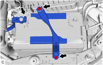
Loosen the nut, and separate the positive (+) battery terminal.
-
Remove the bolt and nut.
-
Remove the battery clamp sub-assembly and battery clamp bolt.
-
Remove the battery, battery insulator and battery tray from the battery carrier bracket sub-assembly.
-
-
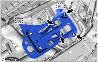
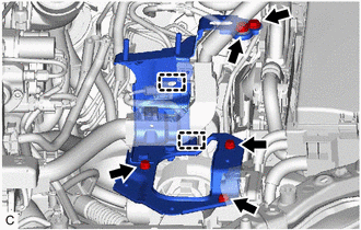
REMOVE BATTERY CARRIER BRACKET SUB-ASSEMBLY
-
Disconnect the 2 clamps and engine wire from the battery carrier bracket sub-assembly.
-
Remove the 4 bolts and battery carrier bracket sub-assembly.
-
-
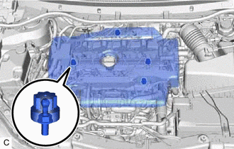
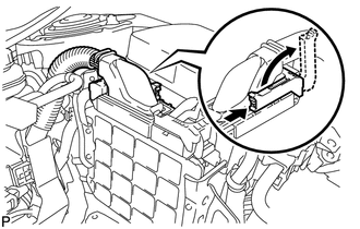
DISCONNECT NO.2 VACUUM TRANSMITTING HOSE ASSEMBLY
-
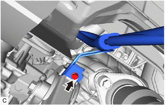
Slide the clip and disconnect the No. 2 vacuum transmitting hose assembly from the intake manifold.
-
-
REMOVE NO. 3 AIR HOSE
-
REMOVE AIR CLEANER CAP SUB-ASSEMBLY
-
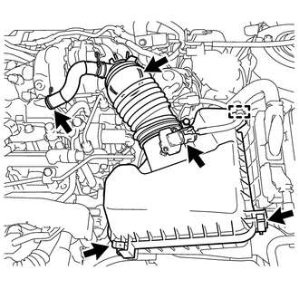
Disconnect the mass air flow meter connector.
-
Slide the clip and disconnect the No. 2 ventilation hose.
-
Slide the hose clamp and disconnect the air cleaner hose.
-
Disengage the 2 lock clamps and remove the air cleaner cap sub-assembly.
-
-
REMOVE AIR CLEANER CASE SUB-ASSEMBLY
-
Remove the air cleaner filter element sub-assembly from the air cleaner case sub-assembly.
-
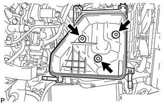
Remove the 3 bolts and air cleaner case sub-assembly.
-
-
REMOVE FUEL FILTER ASSEMBLY
-
DISCONNECT HOSES AND CONNECTORS
-
Remove the No. 1 engine room relay block cover from the engine room relay block.
-
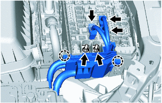
Disconnect the 3 connectors from the engine room relay block.
-
Remove the 2 nuts from the engine room relay block.
-
Disengage the 2 claws and remove the wire harness from the engine room relay block.
-
Remove the bolt and disconnect the No. 3 engine wire from the manual transaxle assembly.
-
Disengage the 2 clamps from the air cleaner bracket.
-
Remove the 5 bolts, air cleaner bracket with the fuel filter support and glow plug relay assembly.
-
Raise the lever while pushing the lock on the lever, and disconnect the ECM connector.
Note
After disconnecting the connector, make sure that dirt, water or other foreign matter does not contact the connecting parts of the connector.
-
-
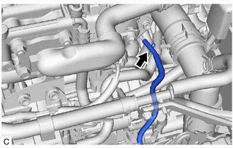
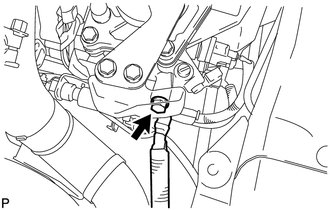
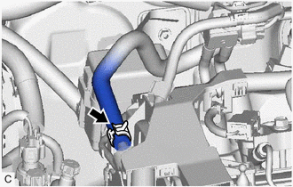
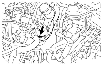
DISCONNECT VACUUM PUMP HOSE
-
Slide the clip and disconnect the vacuum pump hose from the cylinder head cover sub-assembly.
-
-
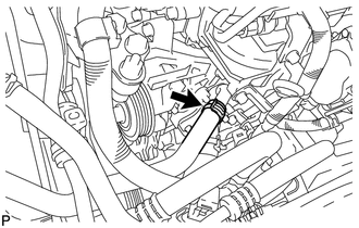
DISCONNECT INLET HEATER WATER HOSE
-
Slide the clip and disconnect the inlet heater water hose from the cylinder head sub-assembly.
-
-
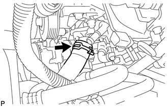
DISCONNECT OUTLET HEATER WATER HOSE
-
Slide the clip and disconnect the outlet heater water hose from the cylinder head sub-assembly.
-
-
DISCONNECT NO. 1 RADIATOR HOSE
-
Slide the clip and disconnect the No. 1 radiator hose from the cylinder head sub-assembly.
-
-
REMOVE INTERCOOLER AIR HOSE
-
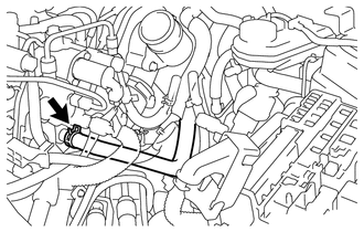
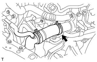
DISCONNECT WATER BY-PASS HOSE
-
Slide the clip and disconnect the water by-pass hose from the No. 4 water by-pass pipe.
-
-
DISCONNECT NO. 2 RADIATOR HOSE
-
Slide the clip and disconnect the No. 2 radiator hose from the water inlet housing.
-
-
REMOVE INJECTOR DRIVER
-
REMOVE FRONT SUSPENSION MEMBER REINFORCEMENT RH
-
REMOVE V-RIBBED BELT
-
DISCONNECT SUCTION HOSE SUB-ASSEMBLY (w/ Air Conditioning System)
-
DISCONNECT DISCHARGE HOSE SUB-ASSEMBLY (w/ Air Conditioning System)
-
REMOVE COMPRESSOR ASSEMBLY WITH PULLEY (w/ Air Conditioning System)
-
DISCONNECT TRANSMISSION CONTROL CABLE ASSEMBLY
-
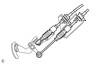
Remove the 2 clips and disconnect the transmission control cable assembly from the manual transaxle assembly.
-
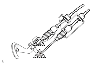
Remove the 2 clips and disconnect the transmission control cable assembly from the control cable bracket.
-
Remove the bolt and disconnect the transmission control cable assembly from the rear engine mounting insulator.
-
-
DISCONNECT CLUTCH RELEASE CYLINDER ASSEMBLY
-
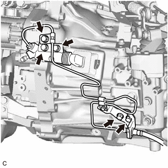
Remove the 5 bolts and disconnect the clutch release cylinder assembly and flexible hose bracket.
-
-
SECURE STEERING WHEEL
-
REMOVE COLUMN HOLE COVER SILENCER SHEET
-
REMOVE NO. 2 STEERING INTERMEDIATE SHAFT ASSEMBLY
-
REMOVE NO. 1 STEERING COLUMN HOLE COVER SUB-ASSEMBLY
-
REMOVE FRONT CENTER FLOOR BRACE SUB-ASSEMBLY
-
REMOVE FRONT EXHAUST PIPE ASSEMBLY
-
REMOVE FRONT DRIVE SHAFT ASSEMBLY
-
REMOVE FRONT ENGINE MOUNTING BRACKET LOWER REINFORCEMENT (w/ Reinforcement)
-
REMOVE FRONT SUSPENSION MEMBER REINFORCEMENT LH
-
REMOVE FRONT SUSPENSION MEMBER REAR BRACE LH
-
REMOVE FRONT SUSPENSION MEMBER REAR BRACE RH
Tech Tips
Perform the same procedure as the LH side.
-
REMOVE FRONT SUSPENSION CROSSMEMBER SUB-ASSEMBLY
-
REMOVE ENGINE ASSEMBLY WITH TRANSAXLE
-
Set an engine lifter.
Note
-
Place a height adjustment attachment and plate lift attachments under the engine assembly with transaxle.
-
Do not position the height adjustment attachment or plate lift attachments under the front crossmember sub-assembly.
-
Do not perform any procedure while the engine assembly with transaxle is suspended because doing so may cause the engine assembly with transaxle to drop, resulting in injury. However, the engine assembly with transaxle needs to be suspended when it is installed to or removed from an engine stand.
-
-
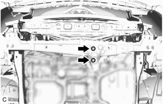
Remove the 2 bolts to disconnect the front engine mounting insulator from the front crossmember sub-assembly.
-
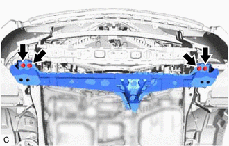
Remove the 4 bolts and front crossmember sub-assembly.
-
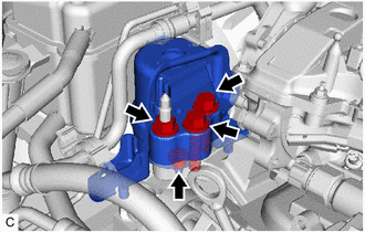
Remove the 2 bolts and 2 nuts and disconnect the engine mounting insulator sub-assembly RH.
-
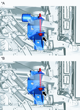
*A Type A *B Type B Remove the through bolt and nut, and separate the engine mounting insulator LH.
Tech Tips
When removing the through bolt, keep the nut from rotating.
-
Carefully remove the engine assembly with transaxle from the vehicle.
Note
Make sure that the engine is clear of all wiring and hoses.
-
-
REMOVE FRONT ENGINE MOUNTING INSULATOR
Tech Tips
Perform this procedure only when replacement of the front engine mounting insulator is necessary.
-
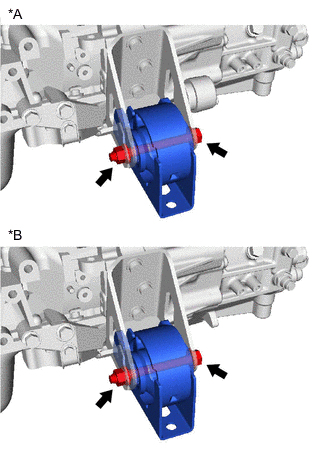
*A Type A *B Type B Remove the through bolt, nut and separate the front engine mounting insulator.
Tech Tips
When removing the through bolt, keep the nut from rotating.
-
-
REMOVE REAR ENGINE MOUNTING INSULATOR
Tech Tips
Perform this procedure only when replacement of the rear engine mounting insulator is necessary.
-
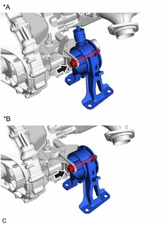
*A Type A *B Type B Remove the through bolt and separate the rear engine mounting insulator.
-
-
REMOVE ENGINE MOUNTING INSULATOR LH
Tech Tips
Perform this procedure only when replacement of the engine mounting insulator LH is necessary.
-
Remove the 4 bolts and engine mounting insulator LH from the vehicle body.
-
-
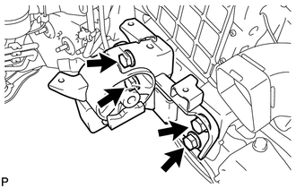
REMOVE ENGINE MOUNTING INSULATOR SUB-ASSEMBLY RH
Tech Tips
Perform this procedure only when replacement of the engine mounting insulator sub-assembly RH is necessary.
-
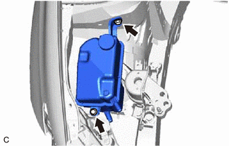
Remove the 2 bolts and disconnect the radiator reservoir tank assembly.
-
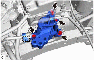
Remove the bolt and separate the cooler pipe clamp bracket from the engine mounting insulator sub-assembly RH.
-
Disconnect the cooler pipe clamp from the engine mounting insulator sub-assembly RH.
-
Remove the 3 bolts and engine mounting insulator sub-assembly RH from the vehicle body.
-
-
INSTALL ENGINE HANGERS
-

*1 No. 1 Engine Hanger (12281-26040) *2 No. 2 Engine Hanger (12282-26010) 
BOLT (91552-81025 or 90105-W0042) Install No. 1 engine hanger and No. 2 engine hanger with the 2 bolts.
- Torque:
- 40 N*m { 408 kgf*cm, 30 ft.*lbf }
Tech Tips
-
Insert the claw of the No. 1 engine hanger into the hole of the cylinder head sub-assembly.
-
Fit the fork part of the No. 2 engine hanger onto the rib of the cylinder head sub-assembly.
-
Using an engine sling device and a chain block, suspend the engine assembly with transaxle.
-
-
DISCONNECT ENGINE WIRE
-
REMOVE NO. 1 AIR TUBE
-
REMOVE STARTER ASSEMBLY
-
REMOVE OIL PAN INSULATOR
-
REMOVE STIFFENER PLATE LH
-
REMOVE STIFFENER PLATE RH
-
REMOVE ENGINE WIRE
-
Disconnect the connectors and detach the clamps securing the engine wire to the engine, remove the bracket bolts and disconnect the engine wire.
-
-
REMOVE MANUAL TRANSAXLE ASSEMBLY
-
REMOVE CLUTCH COVER ASSEMBLY
-
REMOVE CLUTCH DISC ASSEMBLY
-
REMOVE FLYWHEEL SUB-ASSEMBLY
-
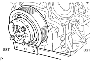
Hold the crankshaft pulley with SST.
- SST
- 09213-58014 ( 91551-80840 )
- 09330-00021
-
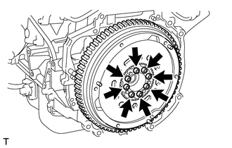
Using a T55 "TORX" socket wrench, remove the 8 bolts and flywheel sub-assembly.
-
-
INSTALL ENGINE TO ENGINE STAND
-
Install the engine to an engine stand, and remove the sling device and chain block from the engine.
Note
-
Adjust the angle of the sling device carefully to prevent the engine assembly or engine hanger from deforming or becoming damaged.
-
Servicing an engine assembly while it is hanging is dangerous. This can be done only when installing/removing the engine assembly to/from an engine stand.
-
-
-
REMOVE ENGINE HANGER
-
Remove the 2 bolts and No. 1 engine hanger and No. 2 engine hanger.
-