ECD SYSTEM(w/ Glow Plug Controller), Diagnostic DTC:P0500
| DTC Code | DTC Name |
|---|---|
| P0500 | Vehicle Speed Sensor |
DESCRIPTION
The wheel speed sensor monitors the wheel rotation speed and sends a signal to the skid control ECU.
The skid control ECU converts the wheel speed signal into a 4-pulse signal and transmits it to the ECM via the combination meter. The ECM determines the vehicle speed based on the frequency of the pulse signal.
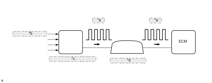
| *a | 4-Pulse |
| *b | from Wheel Speed Sensor |
| *c | Skid Control ECU (Brake Actuator Assembly) |
| *d | Combination Meter Assembly |
| DTC No. | Detection Item | DTC Detection Condition | Trouble Area | MIL | Memory |
|---|---|---|---|---|---|
| P0500 | Vehicle Speed Sensor | Vehicle speed signal is not input to ECM regardless of whether vehicle is in motion (1 trip detection logic). |
|
- | DTC stored |
Tech Tips
For vehicles with a cruise control system, detection does not start unless the following conditions are met.
-
Speed Limiter Main button status is ON.
-
Cruise control OFF-ON button status is ON.
-
Average time period between speed pulses is a non zero value and frozen for a calibrated time.
-
Sensed vehicle speed from hardware is greater than 25 km/h (16 mph).
-
Engine is running.
| DTC No. | DTC Detection Drive Pattern |
|---|---|
| P0500 | Drive the vehicle at 25 km/h (16 mph) or more |
| DTC No. | Data List |
|---|---|
| P0500 | Vehicle Speed |
WIRING DIAGRAM
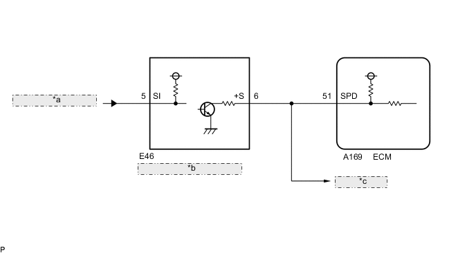
| *a | from Brake Actuator Assembly |
| *b | Combination Meter Assembly |
| *c | to Other ECUs |
CAUTION / NOTICE / HINT
Note
-
When replacing the ECM, the ECM needs Registration and Initialization.
-
Inspect the fuses for circuits related to this system before performing the following inspection procedure.
Tech Tips
-
When the ECM must be replaced, before replacing the ECM, perform the "Learning Values Save" function using the GTS. Then after installing a new ECM, perform all of the initialization and registration procedures for the "Learning Values Write" function by following the instructions shown on the GTS display.
-
Read freeze frame data using the GTS. Freeze frame data records the engine condition when malfunctions are detected. When troubleshooting, freeze frame data can help determine if the vehicle was moving or stationary, if the engine was warmed up or not, and other data from the time the malfunction occurred.
PROCEDURE
-
CHECK OPERATION OF SPEEDOMETER
-
Drive the vehicle and check whether the operation of the speedometer in the combination meter assembly is normal.
Tech Tips
The vehicle speed sensor is operating normally if the speedometer reading is normal.
OK The vehicle speed sensor is operating normally. Result Proceed to OK NG
NG 
CHECK SPEEDOMETER CIRCUIT Click here
OK 
-
-
READ VALUE USING GTS (VEHICLE SPEED)
-
Connect the GTS to the DLC3.
-
Turn the ignition switch to ON and start the engine.
-
Turn the GTS on.
-
Enter the following menus: Powertrain / Engine and ECT / Data List / Vehicle Speed.
Powertrain > Engine and ECT > Data ListTester Display Vehicle Speed -
Drive the vehicle.
-
Read the value displayed on the GTS.
OK Vehicle speeds displayed on GTS and speedometer display are equal. Result Proceed to OK NG
OK
GO TO STEP 10 Click here
NG
-
-
CHECK TERMINAL VOLTAGE (+S VOLTAGE)
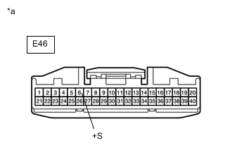
*a Front view of wire harness connector
(to Combination Meter Assembly)
-
Disconnect the combination meter assembly connector.
-
Turn the ignition switch to ON.
-
Measure the voltage according to the value(s) in the table below.
Standard Voltage Tester Connection Condition Specified Condition E46-6 (+S) - Body ground Ignition switch ON 4.5 to 5.5 V Result Proceed to OK NG
NG
CHECK HARNESS AND CONNECTOR (COMBINATION METER ASSEMBLY - ECM) Click here
OK
-
-
CHECK COMBINATION METER ASSEMBLY (SPD SIGNAL WAVEFORM)
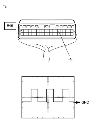
*a Component with harness connected
(Combination Meter Assembly)
-
Turn the ignition switch to ON.
-
Jack up the vehicle.
-
Move the shift lever to neutral.
-
Check the voltage between the terminal of the combination meter assembly and the body ground while a wheel is turned slowly.
Standard Voltage Tester Connection Condition Specified Condition E46-6 (+S) - Body ground Ignition switch ON Voltage generated intermittently Tech Tips
The output voltage should fluctuate up and down, similarly to the diagram, when the wheel is turned slowly.
Result Proceed to OK NG
OK
GO TO STEP 7 Click here
NG
-
-
REPLACE COMBINATION METER ASSEMBLY
-
Replace the combination meter assembly.
For hatchback, wagon: Click here
For sedan: Click here
Result Proceed to NEXT
NEXT
GO TO STEP 10 Click here
-
-
CHECK HARNESS AND CONNECTOR (COMBINATION METER ASSEMBLY - ECM)
-
Disconnect the combination meter assembly connector.
-
Disconnect the ECM connector.
-
Measure the resistance according to the value(s) in the table below.
Standard Resistance Tester Connection Condition Specified Condition E46-6 (+S) - A169-51 (SPD) Always Below 1 Ω Result Proceed to OK NG
NG
REPAIR OR REPLACE HARNESS OR CONNECTOR Click here
OK
-
-
REPLACE ECM
-
Replace the ECM.
Result Proceed to NEXT
NEXT
GO TO STEP 10 Click here
-
-
CHECK SPEEDOMETER CIRCUIT
-
Check the speedometer circuit.
Tech Tips
Inspect the skid control ECU (brake actuator assembly) and speed sensor.
Result Proceed to NEXT
NEXT
GO TO STEP 10 Click here
-
-
REPAIR OR REPLACE HARNESS OR CONNECTOR
-
Repair or replace the harness or connector.
Result Proceed to NEXT
NEXT
-
-
CONFIRM WHETHER MALFUNCTION HAS BEEN SUCCESSFULLY REPAIRED
-
Connect the GTS to the DLC3.
-
Turn the ignition switch to ON.
-
Turn the GTS on.
-
Clear the DTCs.
Powertrain > Engine and ECT > Clear DTCs -
Turn the ignition switch off.
-
Start the engine.
-
Drive the vehicle at 25 km/h (16 mph) or more.
CAUTION:
When performing the confirmation driving pattern, obey all speed limits and traffic laws.
-
Turn the GTS on.
-
Enter the following menus: Powertrain / Engine and ECT / Trouble Codes.
-
Confirm that the DTC is not output.
Powertrain > Engine and ECT > Trouble CodesResult Proceed to NEXT
NEXT 
END
-