ECD SYSTEM(w/ Glow Plug Controller), Diagnostic DTC:P0130, P0136
| DTC Code | DTC Name |
|---|---|
| P0130 | Oxygen Sensor Circuit (Bank 1 Sensor 1) |
| P0136 | O2 (A/F) Sensor Circuit (Bank 1 Sensor 2) |
DESCRIPTION
Refer to DTC P0031.
Tech Tips
Although the DTC titles say oxygen sensor, these DTCs relate to the air fuel ratio sensor.
| DTC No. | Detection Item | DTC Detection Condition | Trouble Area | MIL | Memory |
|---|---|---|---|---|---|
| P0130 | Oxygen Sensor Circuit (Bank 1 Sensor 1) | Condition (A): One of the following conditions is met (2 trip detection logic)
Condition (B): The measured air fuel ratio is higher than high side calculated threshold or lower than low side calculated threshold (1 trip detection logic) |
|
Condition (A): Comes on Condition (B): - |
DTC stored |
| P0136 | O2 (A/F) Sensor Circuit (Bank 1 Sensor 2) | Condition (A): One of the following conditions is met (2 trip detection logic)
Condition (B): The measured air fuel ratio is higher than high side calculated threshold or lower than low side calculated threshold (1 trip detection logic) |
|
Condition (A): Comes on Condition (B): - |
DTC stored |
| DTC No. | DTC Detection Drive Pattern |
|---|---|
| P0130 P0136 |
Condition (A): Vehicle being driven with warm engine Condition (B): One of the following conditions is met
|
CAUTION / NOTICE / HINT
Note
-
When replacing the ECM and/or air fuel ratio sensor, perform ECM Initialization and Registration.
-
Inspect the fuses for circuits related to this system before performing the following procedure.
Tech Tips
-
When the ECM must be replaced, before replacing the ECM, perform the "Learning Values Save" function using the GTS. Then after installing a new ECM, perform all of the initialization and registration procedures for the "Learning Values Write" function by following the instructions shown on the GTS display.
-
Read freeze frame data using the GTS. Freeze frame data records the engine condition when malfunctions are detected. When troubleshooting, freeze frame data can help determine if the vehicle was moving or stationary, if the engine was warmed up or not, and other data from the time the malfunction occurred.
PROCEDURE
-
CHECK ANY OTHER DTCS OUTPUT (IN ADDITION TO DTC P0130 OR P0136)
-
Connect the GTS to the DLC3.
-
Turn the ignition switch to ON and turn the GTS on.
-
Enter the following menus: Powertrain / Engine and ECT / Trouble Codes.
-
Read the DTCs.
Powertrain > Engine and ECT > Trouble CodesResult Result Proceed to DTC P0130 is output A DTC P0136 is output DTC P0130 or P0136 and other DTCs are output B Tech Tips
If any DTCs other than P0130 or P0136 are output, troubleshoot those DTCs first.
B 
GO TO DTC CHART Click here
A 
-
-
PERFORM SIMULATION TEST
-
Interchange the connectors of air fuel ratio sensor (bank 1 sensor 1) and air fuel ratio sensor (bank 1 sensor 2) and connect them.
-
Connect the GTS to the DLC3.
-
Turn the ignition switch to ON and turn the GTS on.
-
Clear the DTCs.
Powertrain > Engine and ECT > Clear DTCs -
Start the engine and allow it to idle until the engine coolant temperature reaches at 70°C (158°F) or higher.
-
Drive the vehicle with a stop-and-go city drive pattern for more than 15 minutes.
CAUTION:
When performing the confirmation driving pattern, obey all speed limits and traffic laws.
-
Enter the following menus: Powertrain / Engine and ECT / Trouble Codes / Pending.
-
Read the pending DTCs.
Powertrain > Engine and ECT > Trouble CodesResult Result Proceed to Output DTC changed from DTC P0130 to P0136 A Output DTC changed from DTC P0136 to P0130 B Output DTC does not change from DTC P0130 to P0136 C Output DTC does not change from DTC P0136 to P0130 D Tech Tips
Other DTCs may be output depending on driving conditions, but check whether the air fuel ratio sensor DTC has changed.
B 
REPLACE AIR FUEL RATIO SENSOR (BANK 1 SENSOR 2) Click here
C
CHECK TERMINAL VOLTAGE (POWER SOURCE OF AIR FUEL RATIO SENSOR (BANK 1 SENSOR 1)) Click here
D
CHECK TERMINAL VOLTAGE (POWER SOURCE OF AIR FUEL RATIO SENSOR (BANK 1 SENSOR 2)) Click here
A
-
-
REPLACE AIR FUEL RATIO SENSOR (BANK 1 SENSOR 1)
-
Replace the air fuel ratio sensor (bank 1 sensor 1).
-
Perform A/F Sensor Compensation Reset.
Result Proceed to NEXT
NEXT
GO TO STEP 15 Click here
-
-
REPLACE AIR FUEL RATIO SENSOR (BANK 1 SENSOR 2)
-
Replace the air fuel ratio sensor (bank 1 sensor 2).
-
Perform A/F Sensor Compensation Reset.
Result Proceed to NEXT
NEXT
GO TO STEP 15 Click here
-
-
CHECK TERMINAL VOLTAGE (POWER SOURCE OF AIR FUEL RATIO SENSOR (BANK 1 SENSOR 1))
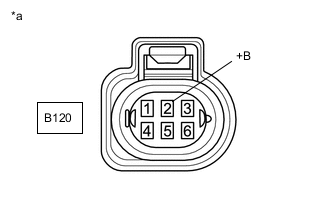
*a Front view of wire harness connector
(to Air Fuel Ratio Sensor (Bank 1 Sensor 1))
-
Disconnect the air fuel ratio sensor (bank 1 sensor 1) connector.
-
Turn the ignition switch to ON.
-
Measure the voltage according to the value(s) in the table below.
Standard Voltage Tester Connection Condition Specified Condition B120-2 (+B) - Body ground Ignition switch ON 11 to 14 V Result Proceed to OK NG
NG
REPAIR OR REPLACE HARNESS OR CONNECTOR (EFI-MAIN NO. 2 RELAY - AIR FUEL RATIO SENSOR (BANK 1 SENSOR 1)) Click here
OK
-
-
CHECK HARNESS AND CONNECTOR (AIR FUEL RATIO SENSOR (BANK 1 SENSOR 1) - ECM)
-
Disconnect the air fuel ratio sensor (bank 1 sensor 1) connector.
-
Disconnect the ECM connector.
-
Measure the resistance according to the value(s) in the table below.
Standard Resistance Tester Connection Condition Specified Condition B120-4 (AF1+) - B212-127 (AF1+) Always Below 1 Ω B120-1 (AF1-) - B212-129 (AF1-) Always Below 1 Ω B120-3 (RE1) - B212-128 (RE1) Always Below 1 Ω B120-5 (HAF1) - B212-46 (HAF1) Always Below 1 Ω B120-4 (AF1+) or B212-127 (AF1+) - Body ground and other terminals Always 10 kΩ or higher B120-1 (AF1-) or B212-129 (AF1-) - Body ground and other terminals Always 10 kΩ or higher B120-3 (RE1) or B212-128 (RE1) - Body ground and other terminals Always 10 kΩ or higher B120-5 (HAF1) or B212-46 (HAF1) - Body ground and other terminals Always 10 kΩ or higher Result Proceed to OK NG
NG
REPAIR OR REPLACE HARNESS OR CONNECTOR Click here
OK
-
-
REPLACE ECM
-
Replace the ECM.
Result Proceed to NEXT
NEXT
GO TO STEP 15 Click here
-
-
REPAIR OR REPLACE HARNESS OR CONNECTOR
Result Proceed to NEXT
NEXT
GO TO STEP 15 Click here
-
REPAIR OR REPLACE HARNESS OR CONNECTOR (EFI-MAIN NO. 2 RELAY - AIR FUEL RATIO SENSOR (BANK 1 SENSOR 1))
Result Proceed to NEXT
NEXT
GO TO STEP 15 Click here
-
CHECK TERMINAL VOLTAGE (POWER SOURCE OF AIR FUEL RATIO SENSOR (BANK 1 SENSOR 2))
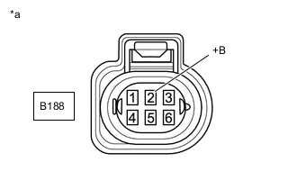
*a Front view of wire harness connector
(to Air Fuel Ratio Sensor (Bank 1 Sensor 2))
-
Disconnect the air fuel ratio sensor (bank 1 sensor 2) connector.
-
Turn the ignition switch to ON.
-
Measure the voltage according to the value(s) in the table below.
Standard Voltage Tester Connection Condition Specified Condition B188-2 (+B) - Body ground Ignition switch ON 11 to 14 V Result Proceed to OK NG
NG
REPAIR OR REPLACE HARNESS OR CONNECTOR (EFI-MAIN NO. 2 RELAY - AIR FUEL RATIO SENSOR (BANK 1 SENSOR 2)) Click here
OK
-
-
CHECK HARNESS AND CONNECTOR (AIR FUEL RATIO SENSOR (BANK 1 SENSOR 2) - ECM)
-
Disconnect the air fuel ratio sensor (bank 1 sensor 2) connector.
-
Disconnect the ECM connector.
-
Measure the resistance according to the value(s) in the table below.
Standard Resistance Tester Connection Condition Specified Condition B188-4 (AF2+) - B212-109 (AF2+) Always Below 1 Ω B188-1 (AF2-) - B212-77 (AF2-) Always Below 1 Ω B188-3 (RE2) - B212-76 (RE2) Always Below 1 Ω B188-5 (HAF2) - B212-16 (HAF2) Always Below 1 Ω B188-4 (AF2+) or B212-109 (AF2+) - Body ground and other terminals Always 10 kΩ or higher B188-1 (AF2-) or B212-77 (AF2-) - Body ground and other terminals Always 10 kΩ or higher B188-3 (RE2) or B212-76 (RE2) - Body ground and other terminals Always 10 kΩ or higher B188-5 (HAF2) or B212-16 (HAF2) - Body ground and other terminals Always 10 kΩ or higher Result Proceed to OK NG
NG
REPAIR OR REPLACE HARNESS OR CONNECTOR Click here
OK
-
-
REPLACE ECM
-
Replace the ECM.
Result Proceed to NEXT
NEXT
GO TO STEP 15 Click here
-
-
REPAIR OR REPLACE HARNESS OR CONNECTOR
Result Proceed to NEXT
NEXT
GO TO STEP 15 Click here
-
REPAIR OR REPLACE HARNESS OR CONNECTOR (EFI-MAIN NO. 2 RELAY - AIR FUEL RATIO SENSOR (BANK 1 SENSOR 2))
Result Proceed to NEXT
NEXT
-
CONFIRM WHETHER MALFUNCTION HAS BEEN SUCCESSFULLY REPAIRED
-
Check that the connectors that were interchanged during the simulation test in step 2 have been returned to their original conditions.
-
Connect the GTS to the DLC3.
-
Turn the ignition switch to ON and turn the GTS on.
-
Clear the DTCs.
Powertrain > Engine and ECT > Clear DTCs -
Start the engine and allow it to idle until the engine coolant temperature reaches at 70°C (158°F) or higher.
-
Drive the vehicle with a stop-and-go city drive pattern for more than 15 minutes.
CAUTION:
When performing the confirmation driving pattern, obey all speed limits and traffic laws.
-
Enter the following menus: Powertrain / Engine and ECT / Trouble Codes / Pending.
-
Confirm that the pending DTC is not output again.
Powertrain > Engine and ECT > Trouble CodesResult Proceed to NEXT
NEXT
END
-