AIR CONDITIONING UNIT INSTALLATION
CAUTION / NOTICE / HINT
Tech Tips
-
Use the same procedure for RHD and LHD vehicles.
-
The procedure listed below is for LHD vehicles.
PROCEDURE
-
INSTALL BLOWER ASSEMBLY
-
INSTALL NO. 3 AIR DUCT SUB-ASSEMBLY
-
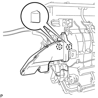
Attach the 2 claws to install the No. 3 air duct sub-assembly.
-
-
INSTALL NO. 2 AIR DUCT SUB-ASSEMBLY
-
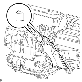
Attach the 2 claws to install the No. 2 air duct sub-assembly.
-
-
TEMPORARILY INSTALL AIR CONDITIONING UNIT
-
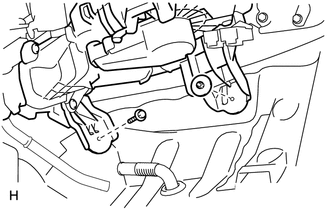
Temporarily install the air conditioning unit with the bolt and nut.
Note
-
Be sure to support the air conditioning unit when installing it because failure to do so may cause the bracket of the air conditioning unit to break.
-
When installing the air conditioning unit, eliminate static electricity by touching the vehicle body to prevent the components from being damaged.
-
-
-
INSTALL INSTRUMENT PANEL REINFORCEMENT ASSEMBLY
-
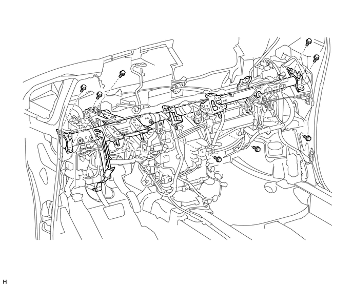
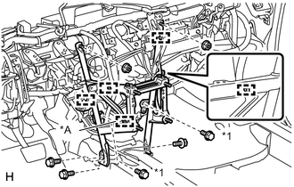
Install the instrument panel reinforcement assembly with the 8 bolts.
-
Connect each connector.
-
Attach each clamp.
-
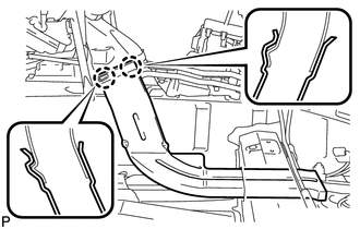
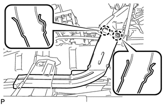
Connect the wire harness and junction block and install each bolt.
- Torque:
- for bolt A
- 24 N*m { 245 kgf*cm, 18 ft.*lbf }
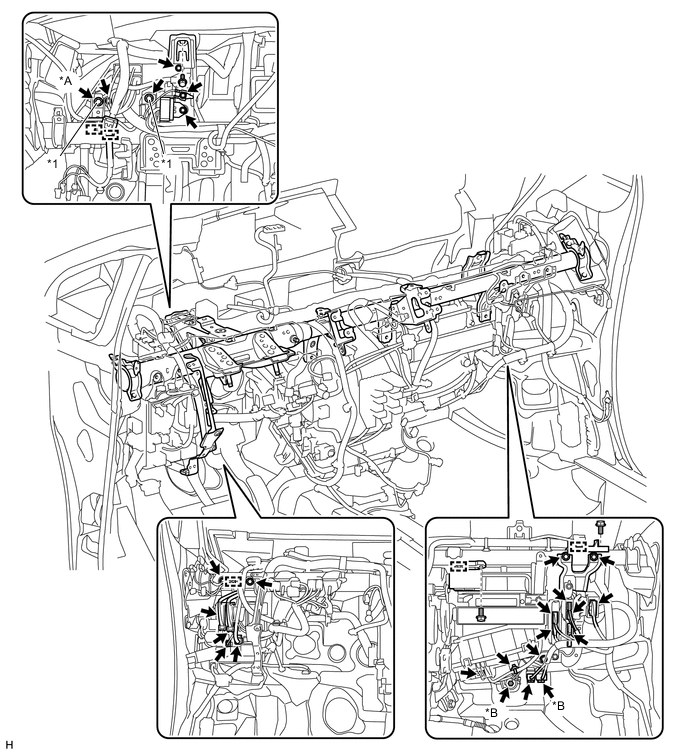
Text in Illustration *A except Manual Transaxle *B w/ PTC Heater *1 Specified Torque Bolt A - - -
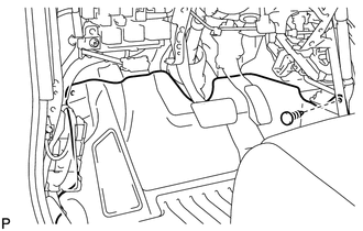
Attach each clamp and connect the wire harness.
-
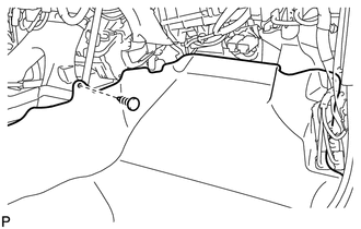
Install the ground wire with the 2 bolts.
-
-
INSTALL AIR CONDITIONING UNIT
-
Tighten the bolt of the air conditioning unit.
- Torque:
- 9.8 N*m { 100 kgf*cm, 87 in.*lbf }
-
Tighten the nut of the air conditioning unit.
- Torque:
- 9.8 N*m { 100 kgf*cm, 87 in.*lbf }
-
Connect the drain cooler hose.
-
-
INSTALL REAR NO. 2 AIR DUCT
-
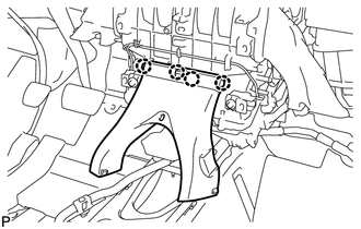
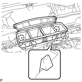
Attach the 4 claws to install the rear No. 2 air duct.
-
-
INSTALL INSTRUMENT PANEL BRACE ASSEMBLY
Text in Illustration *A except Manual Transaxle *1 Screw
-
Install the instrument panel brace assembly with the 3 bolts, 2 screws and 2 nuts.
- Torque:
- Screw
- 9.8 N*m { 100 kgf*cm, 87 in.*lbf }
-
Attach each clamp.
-
Connect the connector.
-
-
INSTALL CENTER INSTRUMENT PANEL TO COWL BRACE
-
Install the center instrument panel to cowl brace with the 2 bolts.
-
-
INSTALL LOWER DEFROSTER NOZZLE ASSEMBLY
-
Attach the 6 claws to install the lower defroster nozzle assembly.
-
-
INSTALL NO. 1 AIR DUCT SUB-ASSEMBLY
-
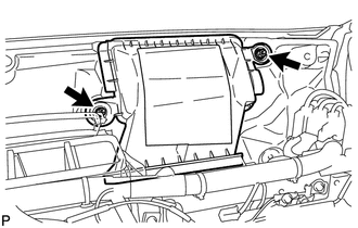
Install the No. 1 air duct sub-assembly with the 2 nuts.
- Torque:
- 9.8 N*m { 100 kgf*cm, 87 in.*lbf }
-
-
INSTALL REAR NO. 1 AIR DUCT
-
Attach the 2 claws to install the rear No. 1 air duct.
-
Install the floor carpet with the clip.
-
-
INSTALL REAR NO. 3 AIR DUCT
-
Attach the 2 claws to install the rear No. 3 air duct.
-
Install the floor carpet with the clip.
-
-
INSTALL LOWER INSTRUMENT PANEL SUB-ASSEMBLY
-
INSTALL COWL SIDE TRIM BOARD LH
-
INSTALL FRONT DOOR SCUFF PLATE LH
-
INSTALL COWL SIDE TRIM BOARD RH
-
INSTALL FRONT DOOR SCUFF PLATE RH
-
INSTALL STEERING COLUMN ASSEMBLY
-
INSTALL INSTRUMENT PANEL SAFETY PAD SUB-ASSEMBLY
-
CONNECT HEATER OUTLET WATER HOSE AND HEATER INLET WATER HOSE
-
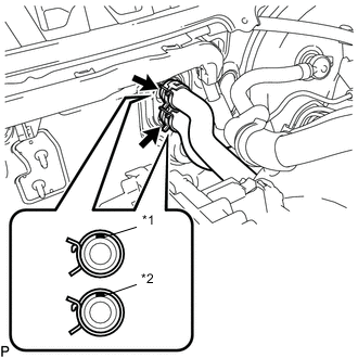
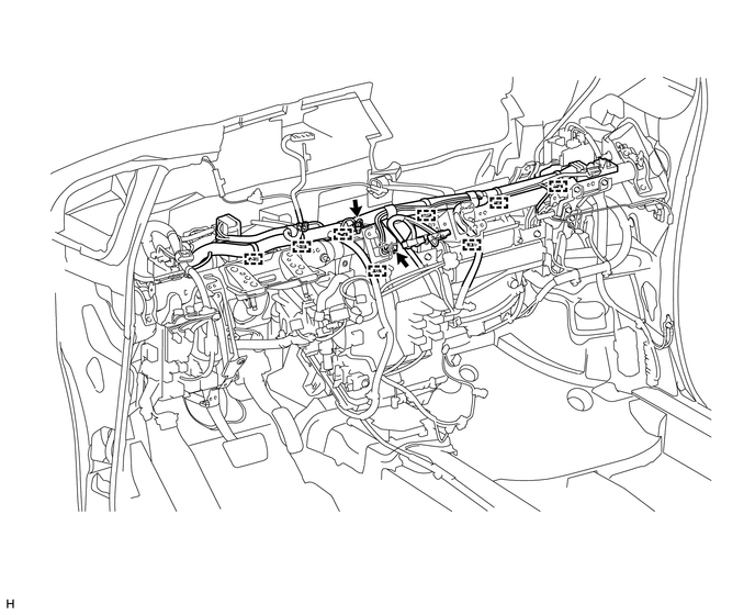
Text in Illustration *1 Paint Mark (Width: 5 mm) *2 Paint Mark (Width: 2 mm) Connect the heater outlet water hose and heater inlet water hose with the paint mark facing up and attach the clip shown in the illustration.
-
-
CONNECT AIR CONDITIONER TUBE AND ACCESSORY ASSEMBLY (for HFO-1234yf(R1234yf))
-
Remove the attached vinyl tape from the pipe and air conditioning unit.
-
Sufficiently apply compressor oil to 2 new O-rings and the fitting surface of the air conditioning tube and accessory.
Compressor oil ND-OIL 12 or equivalent -
Install the 2 O-rings to the air conditioning tube and accessory.
-
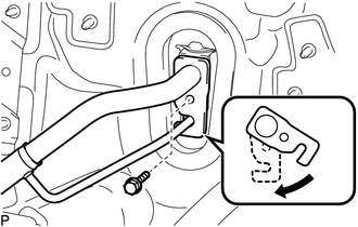
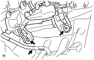
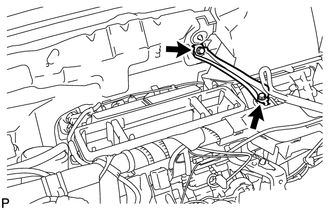
Securely connect the air conditioning tube and accessory to the air conditioning unit.
-
Move the hook connector in the direction indicated by the arrow in the illustration and install the bolt.
- Torque:
- 9.8 N*m { 100 kgf*cm, 87 in.*lbf }
-
-
CONNECT AIR CONDITIONING TUBE AND ACCESSORY ASSEMBLY (for HFC-134a(R134a))
-
Remove the attached vinyl tape from the tube and air conditioning unit.
-
Sufficiently apply compressor oil to a new O-ring and the fitting surface of the air conditioning tube assembly.
Compressor oil ND-OIL 8 or equivalent -
Install the O-ring to the air conditioning tube and accessory.
-
Connect the air conditioner tube and accessory assembly.
-
-
CONNECT SUCTION PIPE SUB-ASSEMBLY (for HFC-134a(R134a))
-
Remove the attached vinyl tape from the pipe and air conditioning unit.
-
Sufficiently apply compressor oil to a new O-ring and the fitting surface of the suction pipe sub-assembly.
Compressor oil ND-OIL 8 or equivalent -
Install the O-ring to the suction pipe sub-assembly.
-
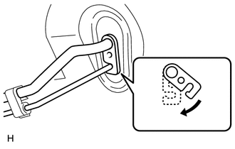
Securely connect the suction pipe to the air conditioning unit.
-
Move the hook connector in the direction indicated by the arrow in the illustration and install the bolt.
- Torque:
- 9.8 N*m { 100 kgf*cm, 87 in.*lbf }
-
-
INSTALL OUTER COWL TOP PANEL
-
INSTALL DIFFERENTIAL PRESSURE SENSOR ASSEMBLY (for DPF)
-
INSTALL WINDSHIELD WIPER MOTOR AND LINK ASSEMBLY
-
INSTALL COWL TOP VENTILATOR LOUVER LH
-
INSTALL COWL TOP VENTILATOR LOUVER RH
-
INSTALL HOOD TO COWL TOP SEAL
-
INSTALL FRONT WIPER ARM AND BLADE ASSEMBLY LH
-
INSTALL FRONT WIPER ARM AND BLADE ASSEMBLY RH
-
INSTALL FRONT WIPER ARM HEAD CAP
-
INSTALL NO. 2 CYLINDER HEAD COVER (for ZR Series Engine)
-
INSTALL NO. 1 ENGINE COVER (for 1WW)
-
CHARGE REFRIGERANT
-
for HFC-134a(R134a):
-
for HFO-1234yf(R1234yf):
-
-
ADD ENGINE COOLANT (for 1ZR-FAE)
-
ADD ENGINE COOLANT (for 2ZR-FAE)
-
ADD ENGINE COOLANT (for 1WW)
-
CONNECT CABLE TO NEGATIVE BATTERY TERMINAL
CAUTION:
When disconnecting the cable, some systems need to be initialized after the cable is reconnected Click here.
-
INSPECT FOR COOLANT LEAK (for 1ZR-FAE)
-
INSPECT FOR COOLANT LEAK (for 2ZR-FAE)
-
INSPECT FOR COOLANT LEAK (for 1WW)
-
CHECK SRS WARNING LIGHT
-
WARM UP ENGINE
-
for HFC-134a(R134a):
-
for HFO-1234yf(R1234yf):
-
-
CHECK FOR REFRIGERANT GAS LEAK
-
for HFC-134a(R134a):
-
for HFO-1234yf(R1234yf):
-