PRE-COLLISION SYSTEM, Diagnostic DTC:C1AA7
| DTC Code | DTC Name |
|---|---|
| C1AA7 | Skid Control Buzzer Circuit |
DESCRIPTION
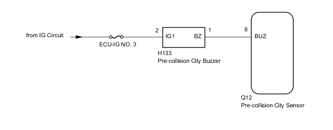
When the pre-collision city sensor uses the pre-collision alarm control to sound a warning, a buzzer signal is output to the pre-collision city buzzer. This DTC is output when the pre-collision city sensor detects a malfunction in the pre-collision city buzzer circuit.
| DTC No. | DTC Detection Condition | Trouble Area |
|---|---|---|
| C1AA7 |
|
|
WIRING DIAGRAM
CAUTION / NOTICE / HINT
Note
-
Inspect the fuses for circuits related to this system before performing the following procedure.
-
When replacing the pre-collision city sensor, replace it with a new one and be sure to initialize the settings. If a pre-collision city sensor which was installed to another vehicle is used, the information stored in the pre-collision city sensor will not match the information from the vehicle and, as a result, a DTC may be stored.
-
If the pre-collision city sensor has been replaced, or the windshield glass has been replaced or removed/installed, be sure to perform Pre-collision City Sensor Learning Click here.
PROCEDURE
-
CHECK PRE-COLLISION CITY BUZZER SOUNDING CONDITION
-
Check the operating condition of the pre-collision city buzzer.
Result Result Proceed to The pre-collision city buzzer is not sounding. A The pre-collision city buzzer is sounding. B
B 
CHECK HARNESS AND CONNECTOR (BUZZER - PRE-COLLISION CITY SENSOR) Click here
A 
-
-
PERFORM ACTIVE TEST USING GTS
-
Connect the GTS to the DLC3.
-
Turn the ignition switch to ON.
-
Turn the GTS on.
-
Enter the following menus: Chassis > PCS/LDA/RSA/LVN > Active Test.
-
Perform the Active Test according to the display on the GTS Click here.
Chassis > PCS/LDA/RSA/LVN > Active Test Tester Display Measurement Item Control Range Diagnostic Note PCS Buzzer Request Sound pre-collision city buzzer ON/OFF Test possible with ignition switch ON and vehicle stopped -
Check that the pre-collision city buzzer sounds when the Active Test "PCS Buzzer Request" is set to ON.
OK The pre-collision city buzzer sounds.
NG
CHECK HARNESS AND CONNECTOR (POWER SOURCE CIRCUIT) Click here
OK
-
-
CHECK FOR DTCS
-
Connect the GTS to the DLC3.
-
Turn the ignition switch to ON.
-
Turn the GTS on.
-
Enter the following menus: Chassis / PCS/LDA/RSA/LVN / Trouble Codes.
-
Clear the DTCs Click here.
-
Enter the following menus: Chassis > PCS/LDA/RSA/LVN > Active Test.
-
Perform the Active Test according to the display on the GTS Click here.
Chassis > PCS/LDA/RSA/LVN > Active Test Tester Display Measurement Item Control Range Diagnostic Note PCS Buzzer Request Sound pre-collision city buzzer ON/OFF Test possible with ignition switch ON and vehicle stopped -
Check for DTCs Click here.
Result Result Proceed to DTC C1A47 is not output A DTC C1A47 is output B
A 
USE SIMULATION METHOD TO CHECK Click here
8
REPLACE PRE-COLLISION CITY SENSOR Click here
-
-
CHECK HARNESS AND CONNECTOR (POWER SOURCE CIRCUIT)
-
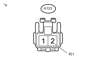
Text in Illustration *a Front view of wire harness connector
(to Pre-collision City Buzzer)
Disconnect the H133 pre-collision city buzzer connector.
-
Measure the voltage according to the value(s) in the table below.
Standard Voltage Tester Connection Condition Specified Condition H133-2 (IG1) - Body ground Ignition switch ON 11 to 14 V H133-2 (IG1) - Body ground Ignition switch off Below 1 V -
Connect the H133 pre-collision city buzzer connector.
NG
REPAIR OR REPLACE HARNESS OR CONNECTOR (POWER SOURCE CIRCUIT)
OK
-
-
CHECK HARNESS AND CONNECTOR (BUZZER - PRE-COLLISION CITY SENSOR)
-
Disconnect the H133 pre-collision city buzzer connector.
-
Disconnect the Q12 pre-collision city sensor connector.
-
Measure the resistance according to the value(s) in the table below.
Standard Resistance Tester Connection Condition Specified Condition H133-1 (BZ) - Q12-8 (BUZ) Always Below 1 Ω H133-1 (BZ) - Body ground Always 10 kΩ or higher -
Connect the Q12 pre-collision city sensor connector.
-
Connect the H133 pre-collision city buzzer connector.
NG
REPAIR OR REPLACE HARNESS OR CONNECTOR (BUZZER - PRE-COLLISION CITY SENSOR)
OK
-
-
INSPECT PRE-COLLISION CITY BUZZER
-
Remove the pre-collision city buzzer Click here.
-
Inspect the pre-collision city buzzer Click here.
OK
REPLACE PRE-COLLISION CITY SENSOR Click here
NG
REPLACE PRE-COLLISION CITY BUZZER Click here
-