TRANSMISSION CONTROL CABLE INSTALLATION
PROCEDURE
-
INSTALL TRANSMISSION CONTROL CABLE ASSEMBLY
-
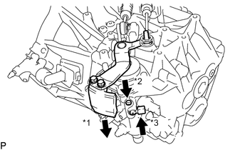
Attach the grommet of the transmission control cable assembly with the 2 nuts.
- Torque:
- 5.0 N*m { 51 kgf*cm, 44 in.*lbf }
-
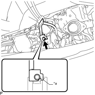
Text in Illustration *a Anti-rotation pin Attach the bracket of the transmission control cable assembly with the bolt.
- Torque:
- 5.0 N*m { 51 kgf*cm, 44 in.*lbf }
Tech Tips
Make sure the anti-rotation pin is contacting the rear engine mount insulator.
-
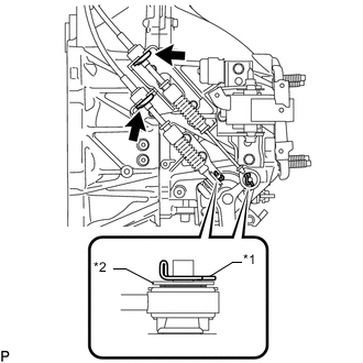
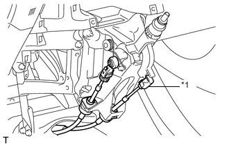
Text in Illustration *1 Clip *2 Metal Washer Plate Connect the 2 cables to the control cable bracket with 2 new clips.
Note
Do not bend the cable more than necessary.
-
Connect the 2 cables to the manual transaxle assembly and install the 2 clips.
Tech Tips
Make sure that the metal washer plate of the shift cable is facing toward the outside of the vehicle.
-
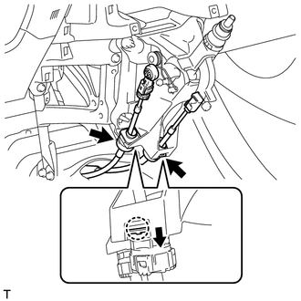
Engage the 2 claws, and install the transmission control cable assembly to the shift lever assembly.
Note
Make sure that the claws are firmly engaged.
-
Text in Illustration *1 Control Shift Cable Install the control shift cable to the shift lever assembly.
-
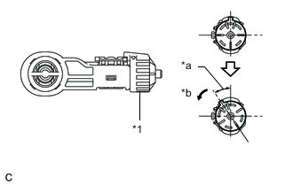
Text in Illustration *1 Stopper *a 34° *b Turn Release the lock of the cable length adjustment structure of the select cable.
-
Turn the stopper.
-
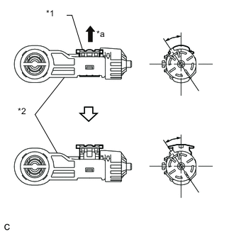
Text in Illustration *1 Lock Piece *2 Case *a Pull Out Pull the lock piece outward from the case to release the lock.
-
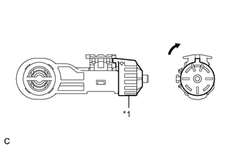
Text in Illustration *1 Stopper 
Return Return the stopper.
-
-
While pressing the shift and select lever shaft (*1) and pin (*2), push in the pin (*3) and check that the shift and select lever shaft is secured at the 1st-2nd gear selected position (the shaft comes to a stop at the position 8 mm (0.315 in.) below the N position).
-
Connect the control select cable to the shift lever assembly.
-
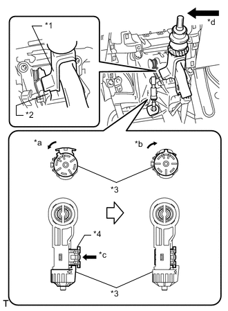
Text in Illustration *1 Slider *2 Inhibitor Wall *3 Stopper *4 Lock Piece *a Turn *b Return *c Push *d Press with a force of 20 N*m (204 kgf*cm, 15 ft.*lbf) Push the slider against the inhibitor wall.
Note
-
Press the slider against the inhibitor wall with a force of 20 N*m (204 kgf*cm, 15 ft.*lbf) as shown in the illustration.
-
Keep pressing the slider against the inhibitor wall until the cable adjustment is completed.
-
Do not pull up the slider.
-
When adjusting the cable, make sure that the shift lever is not in the 1 or 2.
-
-
Lock the cable length adjustment structure of the select cable.
-
Turn the stopper.
-
Push the lock piece into the case.
Note
Do not move the cable in the axial direction.
-
Return the stopper to prevent the lock from being released.
Note
-
Push the lock piece as far as it will go.
-
Confirm whether the cable length adjustment structure is locked securely.
-
-
-
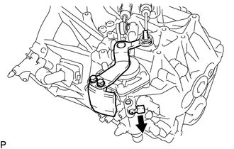
Release the pin that fixes the shift and select lever shaft.
Text in Illustration Pull
-
Pull the pin toward the left front side of the vehicle.
-
-
-
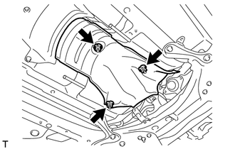
INSTALL FRONT NO. 1 FLOOR HEAT INSULATOR
-
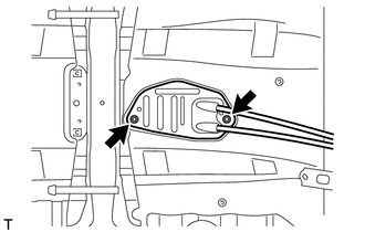
Install the front No. 1 floor heat insulator with the 3 nuts.
- Torque:
- 5.5 N*m { 56 kgf*cm, 49 in.*lbf }
-
-
INSTALL LOWER NO. 1 INSTRUMENT PANEL FINISH PANEL
-
CONNECT NO. 1 AIR TUBE ASSEMBLY
-
CONNECT COMPRESSOR OUTLET ELBOW
-
INSTALL NO. 4 WATER BY-PASS HOSE
-
CONNECT ENGINE WIRE
-
INSTALL AIR CLEANER CASE SUB-ASSEMBLY
-
INSTALL AIR CLEANER FILTER ELEMENT SUB-ASSEMBLY
-
INSTALL AIR CLEANER CAP SUB-ASSEMBLY WITH AIR CLEANER HOSE ASSEMBLY
-
INSTALL BATTERY CARRIER
-
INSTALL BATTERY TRAY
-
INSTALL BATTERY
-
INSTALL BATTERY INSULATOR
-
INSTALL BATTERY CLAMP SUB-ASSEMBLY
-
INSTALL FRONT EXHAUST PIPE ASSEMBLY
-
ADD ENGINE COOLANT
-
CONNECT CABLE TO POSITIVE BATTERY TERMINAL
-
CONNECT CABLE TO NEGATIVE BATTERY TERMINAL
Note
When disconnecting the cable, some systems need to be initialized after the cable is reconnected Click here.
-
INSPECT COOLANT LEAK
-
INSPECT EXHAUST GAS LEAK
-
INSTALL RADIATOR SUPPORT OPENING COVER
-
INSTALL NO. 1 ENGINE COVER
-
INSTALL NO. 1 ENGINE UNDER COVER