EGR COOLER INSTALLATION
PROCEDURE
-
INSTALL EGR VALVE ASSEMBLY
-
INSTALL EGR COOLER ASSEMBLY WITH EGR VALVE ASSEMBLY
-
Install a new water pipe to the EGR cooler assembly.
-
Install a new gasket to the No. 2 EGR pipe sub-assembly.
Tech Tips
Make sure that the claw of the gasket faces the No. 2 EGR pipe sub-assembly.
-
Temporarily install the EGR cooler assembly with EGR valve assembly with the 7 bolts.
-
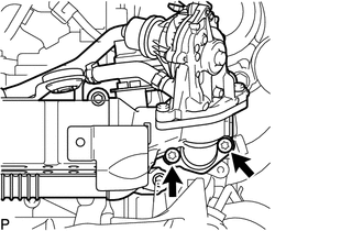
Using a T45 "TORX" socket wrench, tighten the 2 bolts.
- Torque:
- 5.0 N*m { 51 kgf*cm, 44 in.*lbf }
-
Loosen the 2 bolts 90°.
-
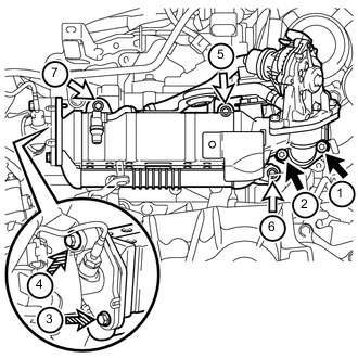
Tighten the 7 bolts labeled A, B and C, and then 2 nuts in the order shown in the illustration.
- Torque:
- for bolt A
- 13 N*m { 133 kgf*cm, 10 ft.*lbf }
- for bolt B
- 19 N*m { 194 kgf*cm, 14 ft.*lbf }
- for bolt C
- 8.0 N*m { 82 kgf*cm, 71 in.*lbf }
Text in Illustration 
Bolt A 
Bolt B 
Bolt C Tech Tips
-
When tightening the bolts labeled A, use a T45 "TORX" socket wrench.
-
When tightening the bolts labeled B, use a 6 mm hexagon wrench.
-
Connect the vacuum hoses to the EGR cooler assembly.
-
Connect the hose clamp to the EGR cooler hose.
-
Attach the clamp and connect the engine wire to the EGR valve assembly.
-
Connect the EGR valve assembly connector.
-
-
INSTALL NO. 1 EXHAUST MANIFOLD HEAT INSULATOR
-
Install the No. 1 exhaust manifold heat insulator with the 2 bolts.
- Torque:
- 8.0 N*m { 82 kgf*cm, 71 in.*lbf }
-
Attach the 2 clamps and connect the engine wire.
-
Attach the 2 clamps and connect the air fuel ratio sensor.
-
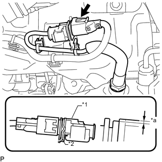
Text in Illustration *1 Air Fuel Ratio Sensor *2 Bracket *a 1.5 mm (0.0591 in.) or less Lower the air fuel ratio sensor connector to the position shown in the illustration and connect the air fuel ratio sensor connector.
-
-
INSTALL NO. 1 TURBO INSULATOR
-
CONNECT FUEL FEED PIPE SUB-ASSEMBLY
-
Connect the fuel feed pipe sub-assembly to the fuel pipe clamp.
-
Connect the vacuum hose to the No. 2 fuel hose.
-
Connect the fuel feed pipe sub-assembly with the 2 bolts.
- Torque:
- 8.0 N*m { 82 kgf*cm, 71 in.*lbf }
-
Attach the 2 clamps and connect the engine wire.
-
-
CONNECT NO. 1 AIR TUBE ASSEMBLY
-
INSTALL NO. 4 WATER BY-PASS HOSE
-
CONNECT ENGINE WIRE
-
CONNECT COMPRESSOR OUTLET ELBOW
-
INSTALL AIR CLEANER CASE SUB-ASSEMBLY
-
INSTALL AIR CLEANER FILTER ELEMENT SUB-ASSEMBLY
-
INSTALL AIR CLEANER CAP SUB-ASSEMBLY WITH AIR CLEANER HOSE ASSEMBLY
-
INSTALL BATTERY CARRIER
-
INSTALL BATTERY TRAY
-
INSTALL BATTERY
-
INSTALL BATTERY INSULATOR
-
INSTALL BATTERY CLAMP SUB-ASSEMBLY
-
INSTALL RADIATOR SUPPORT OPENING COVER
-
CONNECT CABLE TO POSITIVE BATTERY TERMINAL
-
CONNECT CABLE TO NEGATIVE BATTERY TERMINAL
Note
When disconnecting the cable, some systems need to be initialized after the cable is reconnected Click here.
-
ADD ENGINE COOLANT
-
INSPECT FOR COOLANT LEAK
-
INSTALL NO. 1 ENGINE UNDER COVER
-
PERFORM INITIALIZATION
-
Perform EGR learning value reset Click here.
-