FRONT AIR CONDITIONING UNIT REMOVAL

CAUTION / NOTICE / HINT
Note
Set to recirculation mode before removing the air conditioning filter.
Tech Tips
-
Use the same procedures for LHD and RHD vehicles.
-
The procedures listed below are for LHD vehicles.
PROCEDURE
-
REMOVE FRONT FENDER SPLASH SHIELD SUB-ASSEMBLY LH
-
REMOVE FRONT FENDER SPLASH SHIELD SUB-ASSEMBLY RH
-
REMOVE NO. 1 ENGINE UNDER COVER SUB-ASSEMBLY
-
REMOVE UPPER RADIATOR SUPPORT SEAL
-
REMOVE INTERCOOLER ASSEMBLY (for 1VD-FTV)
-
RECOVER REFRIGERANT FROM REFRIGERATION SYSTEM
-
DRAIN ENGINE COOLANT
-
for 3UR-FE:
-
for 1VD-FTV:
-
-
DISCONNECT CABLE FROM NEGATIVE BATTERY TERMINAL
CAUTION:
Wait at least 90 seconds after disconnecting the cable from the negative (-) battery terminal to disable the SRS system.
Note
When disconnecting the cable, some systems need to be initialized after the cable is reconnected Click here.
-
REMOVE V-BANK COVER SUB-ASSEMBLY (for 3UR-FE)
-
DISCONNECT AIR CONDITIONING TUBE AND ACCESSORY ASSEMBLY
-
Remove the bolt.
-
Detach the plate as shown in the illustration.
-
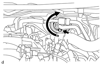
*1 Disconnect tube by hand Disconnect the air conditioning tube and accessory assembly.
Note
-
Do not use a screwdriver or similar tool to disconnect the tube.
-
Seal the openings of the disconnected parts using vinyl tape to prevent moisture and foreign matter from entering them.
-
-
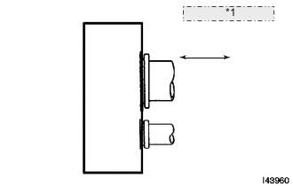
Remove the 2 O-rings from the air conditioning tube and accessory assembly.
-
-
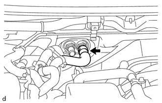
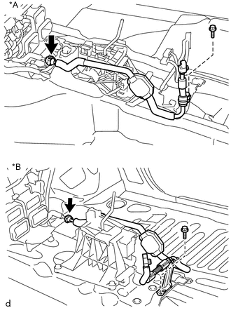
DISCONNECT HEATER WATER OUTLET HOSE A
-
for 3UR-FE:
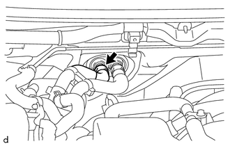
Using pliers, grip the claws of the clip and slide the clip to disconnect the heater water outlet hose A.
Note
-
Do not apply excessive force to the heater water outlet hose A.
-
Prepare a drain pan or cloth in case the coolant leaks.
-
-
for 1VD-FTV:
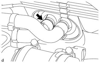
Using pliers, grip the claws of the clip and slide the clip to disconnect the heater water outlet hose A.
Note
-
Do not apply excessive force to the heater water outlet hose A.
-
Prepare a drain pan or cloth in case the coolant leaks.
-
-
-
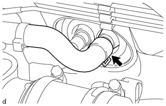
DISCONNECT HEATER WATER INLET HOSE A
-
for 3UR-FE:
Using pliers, grip the claws of the clip and slide the clip to disconnect the heater water inlet hose A.
Note
-
Do not apply excessive force to the heater water inlet hose A.
-
Prepare a drain pan or cloth in case the coolant leaks.
-
-
for 1VD-FTV:
Using pliers, grip the claws of the clip and slide the clip to disconnect the heater water inlet hose A.
Note
-
Do not apply excessive force to the heater water inlet hose A.
-
Prepare a drain pan or cloth in case the coolant leaks.
-
-
-
REMOVE FRONT WIPER MOTOR AND BRACKET
-
REMOVE INSTRUMENT PANEL SUB-ASSEMBLY
-
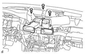
REMOVE CENTER HEATER TO RESISTOR DUCT
-
Remove the 3 clips and remove the center heater to resistor duct.
-
-
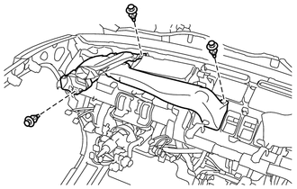
REMOVE NO. 1 HEATER TO RESISTOR DUCT SUB-ASSEMBLY
-
Remove the 3 clips and remove the No. 1 heater to resistor duct sub-assembly.
-
-
REMOVE METER MIRROR SUB-ASSEMBLY
-
REMOVE HEATER TO RESISTOR DUCT ASSEMBLY
-
Remove the 2 clips.
-
Detach the 4 claws and remove the heater to resistor duct assembly.
-
-
REMOVE NO. 3 AIR DUCT SUB-ASSEMBLY
-
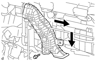
Remove the clip.
-
Detach the 2 claws and remove the No. 3 air duct sub-assembly.
-
-
REMOVE STEERING COLUMN ASSEMBLY
-
REMOVE NO. 1 AIR DUCT SUB-ASSEMBLY
-
Remove the screw and remove the No. 1 air duct sub-assembly.
-
-
REMOVE NO. 2 AIR DUCT SUB-ASSEMBLY
-
Remove the screw and remove the No. 2 air duct sub-assembly.
-
-
REMOVE AIR CONDITIONING AMPLIFIER ASSEMBLY
-
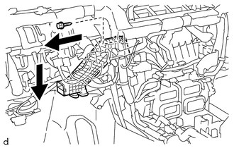
Disconnect the 3 connectors.
-
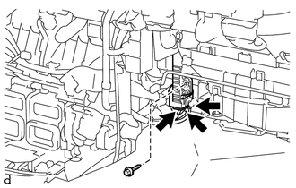
Remove the screw.
-
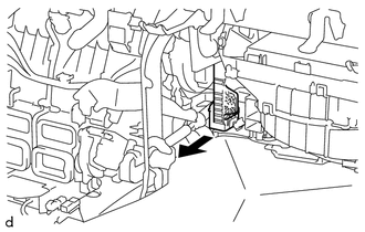
Remove the air conditioning amplifier assembly as shown in the direction indicated by the arrow mark.
-
-
REMOVE INSTRUMENT PANEL WIRE
-
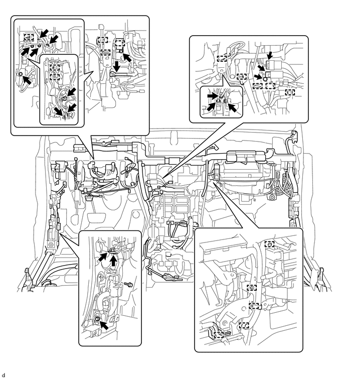
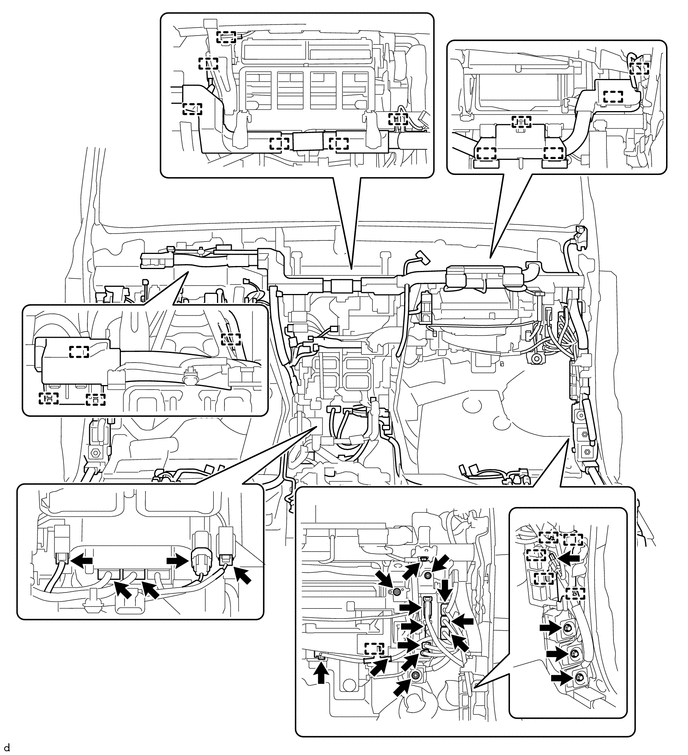
Remove the nuts, bolts, junction block and ground wire.
-
Disconnect the clamps, connectors and instrument panel wire.
-
-
REMOVE INSTRUMENT PANEL SAFETY PAD CAP
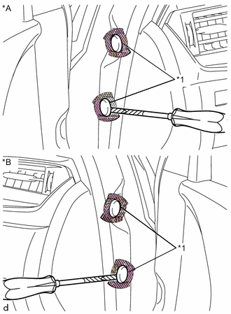
Text in Illustration *A for Driver Side *B for Passenger Side *1 Instrument Panel Safety Pad Cap 
Protective Tape
-
Put protective tape around the instrument panel safety pad cap.
-
Using a screwdriver with its tip wrapped with protective tape, remove the 4 instrument panel safety pad caps.
-
-
REMOVE AIR CONDITIONING HOSE AND ACCESSORY (w/ Cool Box)
Text in Illustration *A for LHD *B for RHD
-
Remove the bolt.
-
Using SST, remove the piping clamp.
- SST
- 09870-00025
-
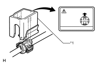
Text in Illustration *1 SST Attach SST to the piping clamp.
Tech Tips
Confirm the direction of the piping clamp claw and SST by referring to the illustration on the caution label.
-
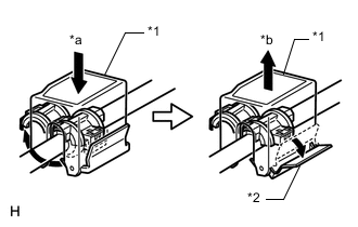
Text in Illustration *1 SST *2 Release Lever *a Push *b Pull Push down SST and release the clamp lock.
Note
Be careful not to deform the tubes when pushing SST.
-
Pull SST slightly and push the release lever, then remove the piping clamp with SST.
-
Remove the piping clamp from SST.
-
Remove the hose and accessory from the liquid tube.
Note
Cap the open fittings immediately to keep moisture or dirt out of the system.
-
Remove the 2 O-rings from the air conditioning hose and accessory.
-
-
REMOVE INSTRUMENT PANEL REINFORCEMENT ASSEMBLY WITH AIR CONDITIONING UNIT ASSEMBLY
Note
-
Be sure to support the air conditioning unit assembly when removing it because failure to do so may cause the bracket of the air conditioning unit assembly to break.
-
When removing the air conditioning unit assembly, eliminate static electricity by touching the vehicle body to prevent the components from being damaged.
-
Remove the instrument panel reinforcement.
-
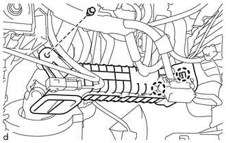
for Engine Room Side:
Remove the grommet.
-
for Engine Room Side:
Remove the bolt
-
for Driver Side:
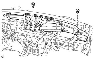
Using a T40 "TORX" socket, remove the 2 "TORX" bolts.
-
for Driver Side:
Remove the bolt.
-
for Passenger Side:
Using a T40 "TORX" socket, remove the 2 "TORX" bolts.
Tech Tips
When removing the bolts, the collars may come off with the bolts.
-
for Passenger Side:
Using a 12 mm hexagon wrench, remove the 2 collars.
-
for Passenger Side:
Remove the 2 nuts.
-
Remove the 3 bolts.
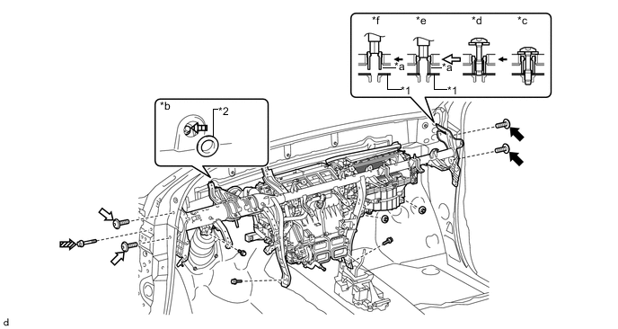
Text in Illustration *1 Instrument Panel Reinforcement Assembly *2 Grommet *a Collar *b for Engine Room Side *c Step 1 *d Step 2 *e Step 3 *f Step 4 
Bolt A 
Bolt B 
Bolt C 
Bolt D
-
-
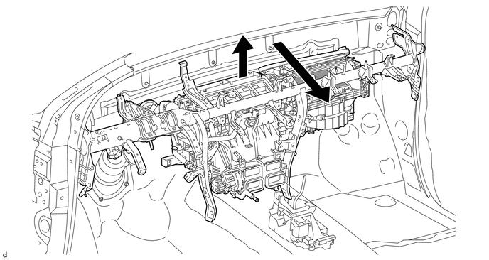
Remove the instrument panel reinforcement assembly with air conditioning unit assembly.
-
-
REMOVE AIR CONDITIONING UNIT ASSEMBLY
-
Remove the 4 bolts, screw and air conditioning unit assembly.
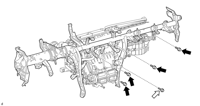
Text in Illustration Bolt Screw
-