NAVIGATION SYSTEM, Diagnostic DTC:B1321, B1322, B1323, B1324, B1325, B1326, B1542, B1563
| DTC Code | DTC Name |
|---|---|
| B1321 | Lost Communication with EMV |
| B1322 | Lost Communication with Display |
| B1323 | Lost Communication with Haptic Device |
| B1324 | Lost Communication with Meter |
| B1325 | Lost Communication with HUD |
| B1326 | Lost Communication with Clock Device (Local-CAN) |
| B1542 | Clock Device Disconnected (Local-CAN) |
| B1563 | Haptic Device Disconnected |
DESCRIPTION
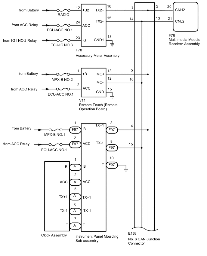
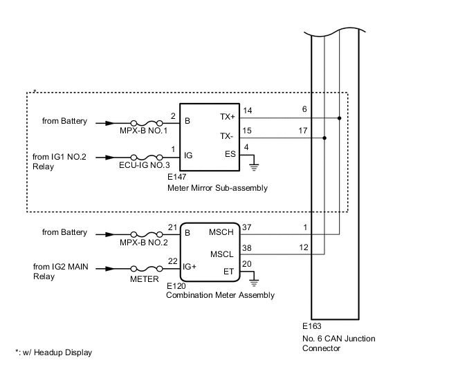
These DTCs are stored when communication between the multi-media module receiver assembly and remote touch (remote operation board), accessory meter assembly, combination meter assembly, meter mirror sub-assembly or clock assembly is not possible.
| DTC Code | DTC Detection Condition | Trouble Area |
|---|---|---|
| B1321 | The components connected via local bus communication do not receive the registration information signal from the multi-media module receiver assembly for 30 seconds or more |
|
| B1322 | The multi-media module receiver assembly does not receive the registration information signal from the accessory meter assembly for 30 seconds or more |
|
| B1323 | The multi-media module receiver assembly does not receive the registration information signal from the remote touch (remote operation board) for 30 seconds or more |
|
| B1324 | After the multi-media module receiver assembly receives a registration information signal, which is sent by the combination meter assembly when the engine switch is turned on (IG), 1 or more times, the multi-media module receiver assembly does not receive the signal for 30 seconds or more |
|
| B1325 | After the multi-media module receiver assembly receives a registration information signal, which is sent by the meter mirror sub-assembly when the engine switch is turned on (IG), 1 or more times, the multi-media module receiver assembly does not receive the signal for 30 seconds or more |
|
| B1326 | After the multi-media module receiver assembly receives a registration information signal, which is sent by the clock assembly when the engine switch is turned on (IG), 1 or more times, the multi-media module receiver assembly does not receive the signal for 30 seconds or more |
|
| B1542 | After the engine switch turned on (ACC), the registration information signal from the clock assembly does not match with the registration history information |
|
| B1563 | The remote touch (remote operation board) is/was not connected while the engine switch is/was on (ACC) or on (IG) |
|
Tech Tips
The multi-media module receiver assembly is the master unit.
WIRING DIAGRAM
CAUTION / NOTICE / HINT
Note
-
Depending on the parts that are replaced during vehicle inspection or maintenance, performing initialization, registration or calibration may be needed. Refer to Precaution for Navigation System Click here.
-
After turning the engine switch off, waiting time may be required before disconnecting the cable from the negative (-) battery terminal. Therefore, make sure to read the disconnecting the cable from the negative (-) battery terminal notices before proceeding with work Click here.
-
Inspect the fuses for circuits related to this system before performing the following procedure.
PROCEDURE
-
CHECK DTC
-
Clear the DTCs Click here.
-
Recheck for DTCs and check that no DTCs are output.
Result Result Proceed to All DTCs are not output A All DTCs are output B DTC B1321 is output C DTC B1322 is output D Other than above E
A 
USE SIMULATION METHOD TO CHECK Click here
B 
CHECK LOCAL BUS Click here
C
CHECK HARNESS AND CONNECTOR (MULTI-MEDIA MODULE RECEIVER ASSEMBLY - NO. 6 CAN JUNCTION CONNECTOR) Click here
D
CHECK HARNESS AND CONNECTOR (ACCESSORY METER ASSEMBLY POWER SOURCE) Click here
E 
-
-
CHECK DTC
-
Recheck for DTCs.
Result Result Proceed to All DTCs are not output A DTCs B1323 or B1563 are output B DTC B1324 is output C DTC B1325 is output D DTCs B1326 or B1542 are output E
A
USE SIMULATION METHOD TO CHECK Click here
B
CHECK HARNESS AND CONNECTOR (REMOTE TOUCH [REMOTE OPERATION BOARD] POWER SOURCE) Click here
C
CHECK HARNESS AND CONNECTOR (COMBINATION METER ASSEMBLY POWER SOURCE) Click here
D
CHECK HARNESS AND CONNECTOR (METER MIRROR SUB-ASSEMBLY POWER SOURCE) Click here
E
CHECK HARNESS AND CONNECTOR (INSTRUMENT PANEL MOULDING SUB-ASSEMBLY POWER SOURCE) Click here
-
-
CHECK LOCAL BUS
-
Disconnect the cable from the negative (-) battery terminal.
-
Measure the resistance according to the value(s) in the table below.
Standard Resistance Tester Connection Condition Specified Condition E163-2 - E163-13 Cable disconnected from negative (-) battery terminal 54 to 69 Ω Result Result Proceed to OK A NG (Below 54 Ω) B NG (70 Ω or higher) C
A
USE SIMULATION METHOD TO CHECK Click here
C
CHECK HARNESS AND CONNECTOR (MULTI-MEDIA MODULE RECEIVER ASSEMBLY - NO. 6 CAN JUNCTION CONNECTOR) Click here
B
-
-
CHECK HARNESS AND CONNECTOR (MULTI-MEDIA MODULE RECEIVER ASSEMBLY - NO. 6 CAN JUNCTION CONNECTOR)
-
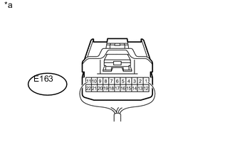
Text in Illustration *a Rear view of wire harness connector
(to No. 6 CAN Junction Connector)
Disconnect the cable from the negative (-) battery terminal.
-
Disconnect the E163 No. 6 CAN junction connector.
-
Connect the F76 multi-media module receiver assembly connector.
-
Measure the resistance according to the value(s) in the table below.
Standard Resistance Tester Connection Condition Specified Condition E163-2 - E163-13 Cable disconnected from negative (-) battery terminal 108 to 132 Ω
NG
CHECK HARNESS AND CONNECTOR (MULTI-MEDIA MODULE RECEIVER ASSEMBLY - NO. 6 CAN JUNCTION CONNECTOR) Click here
OK
-
-
CHECK HARNESS AND CONNECTOR (COMBINATION METER ASSEMBLY - NO. 6 CAN JUNCTION CONNECTOR)
-

Text in Illustration *a Rear view of wire harness connector
(to No. 6 CAN Junction Connector)
Disconnect the cable from the negative (-) battery terminal.
-
Disconnect the E163 No. 6 CAN junction connector.
-
Connect the E120 combination meter assembly connector.
-
Measure the resistance according to the value(s) in the table below.
Standard Resistance Tester Connection Condition Specified Condition E163-1 - E163-12 Cable disconnected from negative (-) battery terminal 108 to 132 Ω
NG
CHECK HARNESS AND CONNECTOR (COMBINATION METER ASSEMBLY - NO. 6 CAN JUNCTION CONNECTOR) Click here
OK
-
-
CHECK HARNESS AND CONNECTOR (REMOTE TOUCH [REMOTE OPERATION BOARD] - NO. 6 CAN JUNCTION CONNECTOR)
-
Text in Illustration *a Rear view of wire harness connector
(to No. 6 CAN Junction Connector)
Disconnect the cable from the negative (-) battery terminal.
-
Disconnect the E163 No. 6 CAN junction connector.
-
Connect the V11 remote touch (remote operation board) connector.
-
Measure the resistance according to the value(s) in the table below.
Standard Resistance Tester Connection Condition Specified Condition E163-5 - E163-16 Cable disconnected from negative (-) battery terminal 200 Ω or higher
NG
CHECK HARNESS AND CONNECTOR (REMOTE TOUCH [REMOTE OPERATION BOARD] - NO. 6 CAN JUNCTION CONNECTOR) Click here
OK
-
-
CHECK HARNESS AND CONNECTOR (ACCESSORY METER ASSEMBLY - NO. 6 CAN JUNCTION CONNECTOR)
-
Text in Illustration *a Rear view of wire harness connector
(to No. 6 CAN Junction Connector)
Disconnect the cable from the negative (-) battery terminal.
-
Disconnect the E163 No. 6 CAN junction connector.
-
Connect the F78 accessory meter assembly connector.
-
Measure the resistance according to the value(s) in the table below.
Standard Resistance Tester Connection Condition Specified Condition E163-3 - E163-14 Cable disconnected from negative (-) battery terminal 200 Ω or higher
NG
CHECK HARNESS AND CONNECTOR (ACCESSORY METER ASSEMBLY - NO. 6 CAN JUNCTION CONNECTOR) Click here
OK
-
-
CHECK VEHICLE CONDITION
-
Check the vehicle condition.
Result Result Proceed to w/ Headup Display A w/o Headup Display B
B
CHECK HARNESS AND CONNECTOR (INSTRUMENT PANEL MOULDING SUB-ASSEMBLY - NO. 6 CAN JUNCTION CONNECTOR) Click here
A
-
-
CHECK HARNESS AND CONNECTOR (METER MIRROR SUB-ASSEMBLY - NO. 6 CAN JUNCTION CONNECTOR)
-
Text in Illustration *a Rear view of wire harness connector
(to No. 6 CAN Junction Connector)
Disconnect the cable from the negative (-) battery terminal.
-
Disconnect the E163 No. 6 CAN junction connector.
-
Connect the E147 meter mirror sub-assembly connector.
-
Measure the resistance according to the value(s) in the table below.
Standard Resistance Tester Connection Condition Specified Condition E163-6 - E163-17 Cable disconnected from negative (-) battery terminal 200 Ω or higher
NG
CHECK HARNESS AND CONNECTOR (METER MIRROR SUB-ASSEMBLY - NO. 6 CAN JUNCTION CONNECTOR) Click here
OK
-
-
CHECK HARNESS AND CONNECTOR (INSTRUMENT PANEL MOULDING SUB-ASSEMBLY - NO. 6 CAN JUNCTION CONNECTOR)
-
Text in Illustration *a Rear view of wire harness connector
(to No. 6 CAN Junction Connector)
Disconnect the cable from the negative (-) battery terminal.
-
Disconnect the E163 No. 6 CAN junction connector.
-
Connect the F97 instrument panel moulding sub-assembly connector.
-
Measure the resistance according to the value(s) in the table below.
Standard Resistance Tester Connection Condition Specified Condition E163-4 - E163-15 Cable disconnected from negative (-) battery terminal 200 Ω or higher
OK
REPLACE NO. 6 CAN JUNCTION CONNECTOR
NG
-
-
CHECK HARNESS AND CONNECTOR (INSTRUMENT PANEL MOULDING SUB-ASSEMBLY - NO. 6 CAN JUNCTION CONNECTOR)
-
Disconnect the cable from the negative (-) battery terminal.
-
Disconnect the F97 instrument panel moulding sub-assembly connector.
-
Connect the E163 No. 6 CAN junction connector.
-
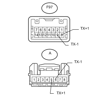
Measure the resistance according to the value(s) in the table below.
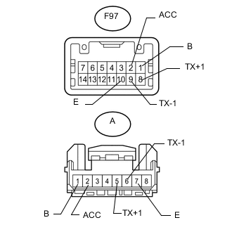
Standard Resistance Tester Connection Condition Specified Condition F97-8 (TX1+) - F97-9 (TX1-) Cable disconnected from negative (-) battery terminal 54 to 69 Ω
NG
REPAIR OR REPLACE HARNESS OR CONNECTOR
OK
-
-
CHECK INSTRUMENT PANEL MOULDING SUB-ASSEMBLY
-
Disconnect the cable from the negative (-) battery terminal.
-
Disconnect the F97 instrument panel moulding sub-assembly connector.
-
Disconnect the A clock assembly connector.
-
Measure the resistance according to the value(s) in the table below.
Standard Resistance Tester Connection Condition Specified Condition F97-8 (TX+1) - A-5 (TX+1) Always Below 1 Ω F97-9 (TX-1) - A-6 (TX-1) Always Below 1 Ω F97-8 (TX+1) or A-5 (TX+1) - Body ground Cable disconnected from negative (-) battery terminal 10 kΩ or higher F97-9 (TX-1) or A-6 (TX-1) - Body ground Cable disconnected from negative (-) battery terminal 10 kΩ or higher
OK
REPLACE CLOCK ASSEMBLY Click here
NG
REPLACE INSTRUMENT PANEL MOULDING SUB-ASSEMBLY Click here
-
-
CHECK HARNESS AND CONNECTOR (METER MIRROR SUB-ASSEMBLY - NO. 6 CAN JUNCTION CONNECTOR)
-
Disconnect the cable from the negative (-) battery terminal.
-
Disconnect the E147 meter mirror sub-assembly connector.
-
Connect the E163 No. 6 CAN junction connector.
-
Measure the resistance according to the value(s) in the table below.
Standard Resistance Tester Connection Condition Specified Condition E147-14 (TX+) - E147-15 (TX-) Cable disconnected from negative (-) battery terminal 54 to 69 Ω
OK
REPLACE METER MIRROR SUB-ASSEMBLY Click here
NG
REPAIR OR REPLACE HARNESS OR CONNECTOR
-
-
CHECK HARNESS AND CONNECTOR (ACCESSORY METER ASSEMBLY - NO. 6 CAN JUNCTION CONNECTOR)
-
Disconnect the cable from the negative (-) battery terminal.
-
Disconnect the F78 accessory meter assembly connector.
-
Connect the E163 No. 6 CAN junction connector.
-
Measure the resistance according to the value(s) in the table below.
Standard Resistance Tester Connection Condition Specified Condition F78-16 (TX2+) - F78-15 (TX2-) Cable disconnected from negative (-) battery terminal 54 to 69 Ω
OK
REPLACE ACCESSORY METER ASSEMBLY Click here
NG
REPAIR OR REPLACE HARNESS OR CONNECTOR
-
-
CHECK HARNESS AND CONNECTOR (REMOTE TOUCH [REMOTE OPERATION BOARD] - NO. 6 CAN JUNCTION CONNECTOR)
-
Disconnect the cable from the negative (-) battery terminal.
-
Disconnect the V11 remote touch (remote operation board) connector.
-
Connect the E163 No. 6 CAN junction connector.
-
Measure the resistance according to the value(s) in the table below.
Standard Resistance Tester Connection Condition Specified Condition V11-13 (MO+) - V11-12 (MO-) Cable disconnected from negative (-) battery terminal 54 to 69 Ω
OK
REPLACE REMOTE TOUCH (REMOTE OPERATION BOARD) Click here
NG
REPAIR OR REPLACE HARNESS OR CONNECTOR
-
-
CHECK HARNESS AND CONNECTOR (COMBINATION METER ASSEMBLY - NO. 6 CAN JUNCTION CONNECTOR)
-
Text in Illustration *a Rear view of wire harness connector
(to No. 6 CAN Junction Connector)
Disconnect the cable from the negative (-) battery terminal.
-
Disconnect the E120 combination meter assembly connector.
-
Connect the E163 No. 6 CAN junction connector.
-
Measure the resistance according to the value(s) in the table below.
Standard Resistance Tester Connection Condition Specified Condition E163-1 - E163-12 Cable disconnected from negative (-) battery terminal 108 to 132 Ω
OK
REPLACE COMBINATION METER ASSEMBLY Click here
NG
REPAIR OR REPLACE HARNESS OR CONNECTOR
-
-
CHECK HARNESS AND CONNECTOR (MULTI-MEDIA MODULE RECEIVER ASSEMBLY - NO. 6 CAN JUNCTION CONNECTOR)
-
Text in Illustration *a Rear view of wire harness connector
(to No. 6 CAN Junction Connector)
Disconnect the cable from the negative (-) battery terminal.
-
Disconnect the F76 multi-media module receiver assembly connector.
-
Connect the E163 No. 6 CAN junction connector.
-
Measure the resistance according to the value(s) in the table below.
Standard Resistance Tester Connection Condition Specified Condition E163-2 - E163-13 Cable disconnected from negative (-) battery terminal 108 to 132 Ω
OK
REPLACE MULTI-MEDIA MODULE RECEIVER ASSEMBLY Click here
NG
REPAIR OR REPLACE HARNESS OR CONNECTOR
-
-
CHECK HARNESS AND CONNECTOR (MULTI-MEDIA MODULE RECEIVER ASSEMBLY - NO. 6 CAN JUNCTION CONNECTOR)
-
Disconnect the cable from the negative (-) battery terminal.
-
Disconnect the F76 multi-media module receiver assembly connector.
-
Connect the E163 No. 6 CAN junction connector.
-
Measure the resistance according to the value(s) in the table below.
Standard Resistance Tester Connection Condition Specified Condition F76-20 (CNH2) - F76-21 (CNL2) Cable disconnected from negative (-) battery terminal 108 to 132 Ω
OK
REPLACE MULTI-MEDIA MODULE RECEIVER ASSEMBLY Click here
NG
-
-
CHECK HARNESS AND CONNECTOR (MULTI-MEDIA MODULE RECEIVER ASSEMBLY - NO. 6 CAN JUNCTION CONNECTOR)
-
Text in Illustration *a Rear view of wire harness connector
(to No. 6 CAN Junction Connector)
Disconnect the cable from the negative (-) battery terminal.
-
Disconnect the E163 No. 6 CAN junction connector.
-
Connect the F76 multi-media module receiver assembly connector.
-
Measure the resistance according to the value(s) in the table below.
Standard Resistance Tester Connection Condition Specified Condition E163-2 - E163-13 Cable disconnected from negative (-) battery terminal 108 to 132 Ω
OK
REPLACE NO. 6 CAN JUNCTION CONNECTOR
NG
REPAIR OR REPLACE HARNESS OR CONNECTOR
-
-
CHECK HARNESS AND CONNECTOR (MULTI-MEDIA MODULE RECEIVER ASSEMBLY - NO. 6 CAN JUNCTION CONNECTOR)
-
Disconnect the cable from the negative (-) battery terminal.
-
Disconnect the F76 multi-media module receiver assembly connector.
-
Measure the resistance according to the value(s) in the table below.
Standard Resistance Tester Connection Condition Specified Condition F76-20 (CNH2) - F76-21 (CNL2) Cable disconnected from negative (-) battery terminal 108 to 132 Ω
OK
REPLACE MULTI-MEDIA MODULE RECEIVER ASSEMBLY Click here
NG
REPAIR OR REPLACE HARNESS OR CONNECTOR
-
-
CHECK HARNESS AND CONNECTOR (ACCESSORY METER ASSEMBLY POWER SOURCE)
-
Disconnect the F78 accessory meter assembly connector.
-
Measure the resistance according to the value(s) in the table below.
Standard Resistance Tester Connection Condition Specified Condition F78-13 (GND1) - Body ground Always Below 1 Ω -
Measure the voltage according to the value(s) in the table below.
Standard Voltage Tester Connection Condition Specified Condition F78-12 (+B2) - Body ground Always 11 to 14 V F78-24 (ACC) - Body ground Engine switch on (ACC) 11 to 14 V F78-23 (IG) - Body ground Engine switch on (IG) 11 to 14 V
NG
REPAIR OR REPLACE HARNESS OR CONNECTOR
OK
-
-
CHECK HARNESS AND CONNECTOR (ACCESSORY METER ASSEMBLY - NO. 6 CAN JUNCTION CONNECTOR)
-
Disconnect the cable from the negative (-) battery terminal.
-
Disconnect the F78 accessory meter assembly connector.
-
Measure the resistance according to the value(s) in the table below.
Standard Resistance Tester Connection Condition Specified Condition F78-16 (TX2+) - F78-15 (TX2-) Cable disconnected from negative (-) battery terminal 54 to 69 Ω
OK
REPLACE ACCESSORY METER ASSEMBLY Click here
NG
REPAIR OR REPLACE HARNESS OR CONNECTOR
-
-
CHECK HARNESS AND CONNECTOR (REMOTE TOUCH [REMOTE OPERATION BOARD] POWER SOURCE)
-
Disconnect the V11 remote touch (remote operation board) connector.
-
Measure the resistance according to the value(s) in the table below.
Standard Resistance Tester Connection Condition Specified Condition V11-15 (GND) - Body ground Always Below 1 Ω -
Measure the voltage according to the value(s) in the table below.
Standard Voltage Tester Connection Condition Specified Condition V11-1 (+B) - Body ground Always 11 to 14 V V11-2 (ACC) - Body ground Engine switch on (ACC) 11 to 14 V
NG
REPAIR OR REPLACE HARNESS OR CONNECTOR
OK
-
-
CHECK HARNESS AND CONNECTOR (REMOTE TOUCH [REMOTE OPERATION BOARD] - NO. 6 CAN JUNCTION CONNECTOR)
-
Disconnect the cable from the negative (-) battery terminal.
-
Disconnect the V11 remote touch (remote operation board) connector.
-
Measure the resistance according to the value(s) in the table below.
Standard Resistance Tester Connection Condition Specified Condition V11-13 (MO+) - V11-12 (MO-) Cable disconnected from negative (-) battery terminal 54 to 69 Ω
OK
REPLACE REMOTE TOUCH (REMOTE OPERATION BOARD) Click here
NG
REPAIR OR REPLACE HARNESS OR CONNECTOR
-
-
CHECK HARNESS AND CONNECTOR (COMBINATION METER ASSEMBLY POWER SOURCE)
-
Disconnect the E120 combination meter assembly connector.
-
Measure the resistance according to the value(s) in the table below.
Standard Resistance Tester Connection Condition Specified Condition E120-20 (ET) - Body ground Always Below 1 Ω -
Measure the voltage according to the value(s) in the table below.
Standard Voltage Tester Connection Condition Specified Condition E120-21 (B) - Body ground Always 11 to 14 V E120-22 (IG+) - Body ground Engine switch on (IG) 11 to 14 V
NG
REPAIR OR REPLACE HARNESS OR CONNECTOR
OK
-
-
CHECK HARNESS AND CONNECTOR (COMBINATION METER ASSEMBLY - NO. 6 CAN JUNCTION CONNECTOR)
-
Disconnect the cable from the negative (-) battery terminal.
-
Disconnect the E120 combination meter assembly connector.
-
Measure the resistance according to the value(s) in the table below.
Standard Resistance Tester Connection Condition Specified Condition E120-37 (MSCH) - E120-38 (MSCL) Cable disconnected from negative (-) battery terminal 108 to 132 Ω
OK
REPLACE COMBINATION METER ASSEMBLY Click here
NG
REPAIR OR REPLACE HARNESS OR CONNECTOR
-
-
CHECK HARNESS AND CONNECTOR (METER MIRROR SUB-ASSEMBLY POWER SOURCE)
-
Disconnect the E147 meter mirror sub-assembly connector.
-
Measure the resistance according to the value(s) in the table below.
Standard Resistance Tester Connection Condition Specified Condition E147-4 (ES) - Body ground Always Below 1 Ω -
Measure the voltage according to the value(s) in the table below.
Standard Voltage Tester Connection Condition Specified Condition E147-2 (B) - Body ground Always 11 to 14 V E147-1 (IG) - Body ground Engine switch on (IG) 11 to 14 V
NG
REPAIR OR REPLACE HARNESS OR CONNECTOR
OK
-
-
CHECK HARNESS AND CONNECTOR (METER MIRROR SUB-ASSEMBLY - NO. 6 CAN JUNCTION CONNECTOR)
-
Disconnect the cable from the negative (-) battery terminal.
-
Disconnect the E147 meter mirror sub-assembly connector.
-
Measure the resistance according to the value(s) in the table below.
Standard Resistance Tester Connection Condition Specified Condition E147-14 (TX-) - E147-15 (TX +) Cable disconnected from negative (-) battery terminal 54 to 69 Ω
OK
REPLACE METER MIRROR SUB-ASSEMBLY Click here
NG
REPAIR OR REPLACE HARNESS OR CONNECTOR
-
-
CHECK HARNESS AND CONNECTOR (INSTRUMENT PANEL MOULDING SUB-ASSEMBLY POWER SOURCE)
-
Disconnect the F97 instrument panel moulding sub-assembly connector.
-
Measure the resistance according to the value(s) in the table below.
Standard Resistance Tester Connection Condition Specified Condition F97-10 (E) - Body ground Always Below 1 Ω -
Measure the voltage according to the value(s) in the table below.
Standard Voltage Tester Connection Condition Specified Condition F97-1 (B) - Body ground Always 11 to 14 V F97-2 (ACC) - Body ground Engine switch on (ACC) 11 to 14 V
NG
REPAIR OR REPLACE HARNESS OR CONNECTOR
OK
-
-
CHECK INSTRUMENT PANEL MOULDING SUB-ASSEMBLY
-
Disconnect the cable from the negative (-) battery terminal.
-
Disconnect the F97 instrument panel moulding sub-assembly connector.
-
Disconnect the A clock assembly connector.
-
Measure the resistance according to the value(s) in the table below.
Standard Resistance Tester Connection Condition Specified Condition F97-1 (B) - A-1 (B) Always Below 1 Ω F97-2 (ACC) - A-2 (ACC) Always Below 1 Ω F97-10 (E) - A-7 (E) Always Below 1 Ω F97-8 (TX+1) or A-5 (TX+1) - Body ground Cable disconnected from negative (-) battery terminal 10 kΩ or higher F97-9 (TX-1) or A-6 (TX-1) - Body ground Cable disconnected from negative (-) battery terminal 10 kΩ or higher
NG
REPLACE INSTRUMENT PANEL MOULDING SUB-ASSEMBLY Click here
OK
-
-
CHECK HARNESS AND CONNECTOR (INSTRUMENT PANEL MOULDING SUB-ASSEMBLY - NO. 6 CAN JUNCTION CONNECTOR)
-
Text in Illustration *a Rear view of wire harness connector
(to No. 6 CAN Junction Connector)
Disconnect the cable from the negative (-) battery terminal.
-
Connect the E163 No. 6 CAN junction connector.
-
Measure the resistance according to the value(s) in the table below.
Standard Resistance Tester Connection Condition Specified Condition E163-4 - E163-15 Cable disconnected from negative (-) battery terminal 54 to 69 Ω
OK
REPLACE NO. 6 CAN JUNCTION CONNECTOR
NG
-
-
CHECK HARNESS AND CONNECTOR (INSTRUMENT PANEL MOULDING SUB-ASSEMBLY - NO. 6 CAN JUNCTION CONNECTOR)
-
Disconnect the cable from the negative (-) battery terminal.
-
Disconnect the F97 instrument panel moulding sub-assembly connector.
-
Disconnect the E163 No. 6 CAN junction connector.
-
Measure the resistance according to the value(s) in the table below.
Standard Resistance Tester Connection Condition Specified Condition E163-4 - E163-15 Always 10 kΩ or higher E163-4 or F97-8 (TX1+) - Body ground Always 10 kΩ or higher E163-15 or F97-9 (TX1-) - Body ground Always 10 kΩ or higher
OK
REPLACE CLOCK ASSEMBLY Click here
NG
REPAIR OR REPLACE HARNESS OR CONNECTOR
-