AUDIO AND VISUAL SYSTEM Mute Signal Circuit between Stereo Component Amplifier and Telematics Transceiver
DESCRIPTION
The DCM (telematics transceiver) sends a mute signal to the stereo component amplifier assembly.
The stereo component amplifier assembly controls the volume according to the mute signal from the DCM (telematics transceiver).
WIRING DIAGRAM
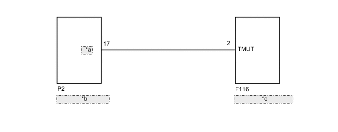
| *a | MUTE |
| *b | DCM (Telematics Transceiver) |
| *c | Stereo Component Amplifier Assembly |
CAUTION / NOTICE / HINT
Note
Depending on the parts that are replaced during vehicle inspection or maintenance, performing initialization, registration or calibration may be needed. Refer to Precaution for Audio and Visual System.
PROCEDURE
-
CHECK DCM (TELEMATICS TRANSCEIVER)
-
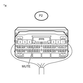
Text in Illustration *a Component with harness connected
(DCM [Telematics Transceiver])
Remove the DCM (telematics transceiver) with its connectors still connected Click here.
-
Measure the voltage according to the value(s) in the table below.
Standard Voltage Tester Connection Condition Specified Condition P2-17 (MUTE) - Body ground Engine switch on (ACC), audio system is playing
→ Emergency call mode
2.0 V or higher
→ Below 1 V
OK 
PROCEED TO NEXT SUSPECTED AREA SHOWN IN PROBLEM SYMPTOMS TABLE Click here
NG 
-
-
CHECK HARNESS AND CONNECTOR (STEREO COMPONENT AMPLIFIER ASSEMBLY - DCM [TELEMATICS TRANSCEIVER])
-
Disconnect the F116 stereo component amplifier assembly connector.
-
Disconnect the P2 DCM (telematics transceiver) connector.
-
Measure the resistance according to the value(s) in the table below.
Standard Resistance Tester Connection Condition Specified Condition F116-2 (TMUT) - P2-17 (MUTE) Always Below 1 Ω F116-2 (TMUT) or P2-17 (MUTE) - Body ground Always 10 kΩ or higher
NG
REPAIR OR REPLACE HARNESS OR CONNECTOR
OK
-
-
CHECK STEREO COMPONENT AMPLIFIER ASSEMBLY
-
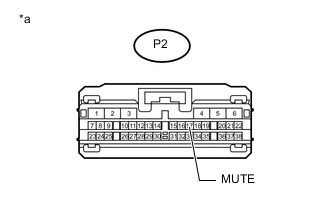
Text in Illustration *a Front view of wire harness connector
(to DCM [Telematics Transceiver])
Reconnect the F116 stereo component amplifier assembly connector.
-
Measure the voltage according to the value(s) in the table below.
Standard Voltage Tester Connection Switch Condition Specified Condition P2-17 (MUTE) - Body ground Engine switch on (ACC) 3.5 V or higher
OK
REPLACE DCM (TELEMATICS TRANSCEIVER) Click here
NG
REPLACE STEREO COMPONENT AMPLIFIER ASSEMBLY Click here
-