FRONT POWER SEAT CONTROL SYSTEM(for RHD) Power Seat Power Easy Access System Function does not Operate
DESCRIPTION
-
When the power switch is off and the shift lever is in P, the power seat slides rearwards when the seat belt tongue plate is disengaged from the front seat inner belt assembly RH (auto away function). Also the power seat slides forward when the seat belt tongue plate is engaged to the front seat inner belt assembly RH with the power switch on (ACC) or on (IG), or the shift lever in P.
for Driver Side:
-
When the vehicle is being driven at a speed below 4 km/h (2.49 mph) and the passenger door is opened, check that the lumbar support, pelvis support and side support move rearwards.
for Front Passenger Side:
WIRING DIAGRAM
-
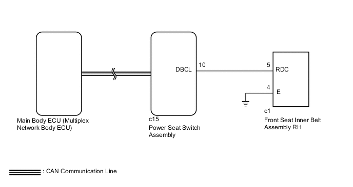
for Driver Side (Standard Seat Type):
-
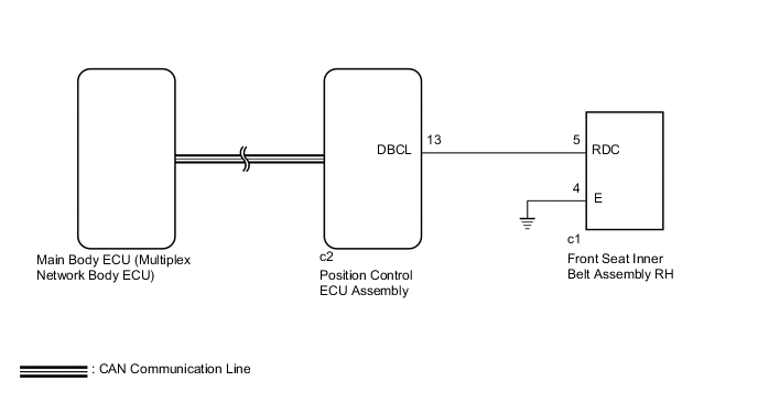
for Driver Side (Sports Seat Type, Luxury Seat Type):
-
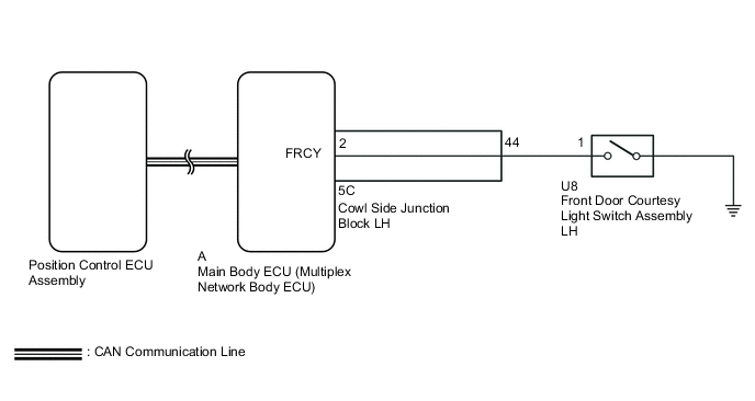
for Front Passenger Side (Luxury Seat Type):
CAUTION / NOTICE / HINT
Note
If the main body ECU (multiplex network body ECU) is replaced, refer to the Service Bulletin.
Tech Tips
Before performing the inspection, check that there are no problems related to the CAN communication system.
PROCEDURE
-
CHECK FRONT POWER SEAT OPERATION
-
Check that each function of the power seat operates normally by using the front power seat switch Click here.
OK Each function of power seat operates normally by using seat switches. Result Result Proceed to Power seat functions operate normally A All power seat functions does not operate B One or more power seat motors does not operate C
B 
GO TO PROBLEM SYMPTOMS TABLE (Front Power Seat does not Operate with Front Power Seat Switch) Click here
C
GO TO PROBLEM SYMPTOMS TABLE (One or more Power Seat Motors do not Operate) Click here
A 
-
-
CHECK SEAT POSITION MEMORY FUNCTION
-
Perform a memory operation and check that the buzzer sounds to indicate the completion of the memory operation Click here.
Note
-
The seat position will not be recorded if the SET switch and 2 or more of the seat memory switches (for example, M1 switch and M2 switch) are pressed simultaneously.
-
If a memorizing operation has failed, release all switches. The seat memory function does not operate unless the switches are released.
OK Seat position memory function operates normally. Result Result Proceed to OK (for Driver Side) A OK (for Front Passenger Side) B NG C -
B 
READ VALUE USING GTS (DOOR COURTESY) Click here
C
GO TO PROBLEM SYMPTOMS TABLE Click here
A
-
-
READ VALUE USING GTS (DRIVER SEAT BUCKLE SW)
-
Connect the GTS to the DLC3.
-
Turn the power switch on (IG).
-
Turn the GTS on.
-
Enter the following menus: Body Electrical / Driver Seat / Data List.
-
Read the Data List according to the display on the GTS.
Driver Seat Tester Display Measurement Item/Range Normal Condition Diagnostic Note Driver Seat Buckle SW Status of the driver's seat belt / ON or OFF ON: Tongue plate is engaged
OFF: Tongue plate is not engaged
- Result Result Proceed to OK (for Standard Seat Type) A OK (for Sports Seat Type, Luxury Seat Type) B NG C
B
REPLACE POSITION CONTROL ECU ASSEMBLY Click here
C
INSPECT FRONT SEAT INNER BELT ASSEMBLY RH Click here
A
-
-
REPLACE POWER SEAT SWITCH ASSEMBLY
-
Temporarily replace the power seat switch assembly with a new or normally functioning one Click here.
NEXT
-
-
CHECK POWER SEAT POWER EASY ACCESS SYSTEM
-
Check that the power seat easy access system operates normally when engaging and disengaging the tongue plate of the seat belt with the shift lever in P Click here.
OK Power seat power easy access system is normal.
OK
END (POWER SEAT SWITCH ASSEMBLY WAS DEFECTIVE)
NG
REPLACE MAIN BODY ECU (MULTIPLEX NETWORK BODY ECU) Click here
-
-
REPLACE POSITION CONTROL ECU ASSEMBLY
-
Temporarily replace the position control ECU assembly with a new or normally functioning one.
-
for Sports Seat Type : Click here
-
for Luxury Seat Type : Click here
-
NEXT
-
-
CHECK POWER SEAT POWER EASY ACCESS SYSTEM
-
Check that the power seat easy access system operates normally when engaging and disengaging the tongue plate of the seat belt with the shift lever in P Click here.
OK Power seat power easy access system is normal.
OK
END (POSITION CONTROL ECU ASSEMBLY WAS DEFECTIVE)
NG
REPLACE POSITION CONTROL ECU ASSEMBLY Click here
-
-
INSPECT FRONT SEAT INNER BELT ASSEMBLY RH
-
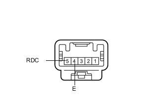
Text in Illustration *a Component without harness connected
(Front Seat Inner Belt Assembly RH)
Remove the front seat inner belt assembly RH Click here.
-
Measure the resistance according to the value(s) in the table below.
Standard Resistance Tester Connection Condition Specified Condition 5 (RDC) - 4 (E) Tongue plate is engaged Below 1 Ω 5 (RDC) - 4 (E) Tongue plate is not engaged 10 kΩ or higher Result Result Proceed to OK (for Standard Seat Type) A OK (for Sports Seat Type, Luxury Seat Type) B NG C
B
CHECK HARNESS AND CONNECTOR (POSITION CONTROL ECU ASSEMBLY - FRONT SEAT INNER BELT ASSEMBLY RH AND GROUND) Click here
C
REPLACE FRONT SEAT INNER BELT ASSEMBLY RH Click here
A
-
-
CHECK HARNESS AND CONNECTOR (POWER SEAT SWITCH ASSEMBLY - FRONT SEAT INNER BELT ASSEMBLY RH AND BODY GROUND)
-
Disconnect the c15 power seat switch assembly connector.
-
Disconnect the c1 front seat inner belt assembly RH connector.
-
Measure the resistance according to the value(s) in the table below.
Standard Resistance Tester Connection Condition Specified Condition c15-10 (DBCL) - c1-5 (RDC) Always Below 1 Ω c1-4 (E) - Body ground Always Below 1 Ω c15-10 (DBCL) - Body ground Always 10 kΩ or higher
OK
REPLACE POWER SEAT SWITCH ASSEMBLY Click here
NG
REPAIR OR REPLACE HARNESS OR CONNECTOR
-
-
CHECK HARNESS AND CONNECTOR (POSITION CONTROL ECU ASSEMBLY - FRONT SEAT INNER BELT ASSEMBLY RH AND GROUND)
-
Disconnect the c2 position control ECU assembly connector.
-
Disconnect the c1 front seat inner belt assembly RH connector.
-
Measure the resistance according to the value(s) in the table below.
Standard Resistance Tester Connection Condition Specified Condition c2-13 (DBCL) - c1-5 (RDC) Always Below 1 Ω c1-4 (E) - Body ground Always Below 1 Ω c2-13 (DBCL) - Body ground Always 10 kΩ or higher Result Result Proceed to OK (for Sport Seat Type) A OK (for Luxury Seat Type) B NG C
A
REPLACE POWER SEAT SWITCH ASSEMBLY Click here
B
REPLACE POSITION CONTROL ECU ASSEMBLY Click here
C
REPAIR OR REPLACE HARNESS OR CONNECTOR
-
-
READ VALUE USING GTS (DOOR COURTESY)
-
Connect the GTS to the DLC3.
-
Turn the power switch on (IG).
-
Turn the GTS on.
-
Enter the following menus: Body Electrical / Main Body / Data List.
-
Read the Data List according to the display on the GTS.
Main Body Tester Display Measurement Item/Range Normal Condition Diagnostic Note FL Door Courtesy Front door courtesy light switch assembly LH signal / ON or OFF ON: Front door LH closed
OFF: Front door LH open
- OK "ON" and "OFF" appears on the screen.
NG
INSPECT FRONT DOOR COURTESY LAMP SWITCH ASSEMBLY LH Click here
OK
-
-
READ VALUE USING GTS (P-DOOR COURTESY)
-
Connect the GTS to the DLC3.
-
Turn the power switch on (IG).
-
Turn the GTS on.
-
Enter the following menus: Body Electrical / Passenger Seat / Data List.
-
Read the Data List according to the display on the GTS.
Passenger Seat Tester Display Measurement Item/Range Normal Condition Diagnostic Note P-Door Courtesy Front door courtesy light switch assembly LH signal / ON or OFF ON: Front door LH closed
OFF: Front door LH open
- OK "ON" and "OFF" appears on the screen.
NG
CHECK MAIN BODY ECU (MULTIPLEX NETWORK BODY ECU) Click here
OK
-
-
READ VALUE USING GTS (VEHICLE SPEED)
-
Connect the GTS to the DLC3.
-
Turn the power switch on (IG).
-
Turn the GTS on.
-
Enter the following menus: Body Electrical / Passenger Seat / Data List.
-
Read the Data List according to the display on the GTS.
Passenger Seat Tester Display Measurement Item/Range Normal Condition Diagnostic Note Vehicle Speed Vehicle speed / Min.: 0 km/h (0 mph), Max.: 255 km/h (158 mph) Almost same as actual vehicle speed - OK Almost same as actual vehicle speed
NG
CHECK MAIN BODY ECU (MULTIPLEX NETWORK BODY ECU) Click here
OK
-
-
CHECK POSITION CONTROL ECU ASSEMBLY
-
Temporarily replace the position control ECU assembly with a new or normally functioning one Click here.
-
Check that the power seat easy access system operates normally Click here.
OK Power seat power easy access system is normal.
OK
END (POSITION CONTROL ECU ASSEMBLY WAS DEFECTIVE)
NG
REPLACE MAIN BODY ECU (MULTIPLEX NETWORK BODY ECU) Click here
-
-
INSPECT FRONT DOOR COURTESY LAMP SWITCH ASSEMBLY LH
-
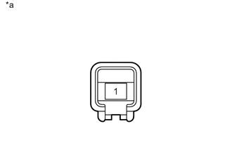
Text in Illustration *a Component without harness connected
(Front Door Courtesy Light Switch Assembly LH)
Remove the front door courtesy light switch LH Click here.
-
Measure the resistance according to the value(s) in the table below.
Standard Resistance Tester Connection Condition Specified Condition 1 - Switch body Pin not pushed Below 1 Ω Pin pushed 10 kΩ or higher
NG
REPLACE FRONT DOOR COURTESY LAMP SWITCH ASSEMBLY LH Click here
OK
-
-
CHECK HARNESS AND CONNECTOR (MAIN BODY ECU [MULTIPLEX NETWORK BODY ECU] - FRONT DOOR COURTESY LIGHT SWITCH ASSEMBLY LH)
-
Disconnect the A main body ECU (multiplex network body ECU) connector.
-
Disconnect the U8 front door courtesy light switch assembly LH connector.
-
Measure the resistance according to the value(s) in the table below.
Standard Resistance Tester Connection Condition Specified Condition A-2 (FLCY) - U8-1 Always Below 1 Ω A-2 (FLCY) - Body ground Always 10 kΩ or higher
OK
REPLACE MAIN BODY ECU (MULTIPLEX NETWORK BODY ECU) Click here
NG
-
-
CHECK HARNESS AND CONNECTOR (COWL SIDE JUNCTION BLOCK LH - FRONT DOOR COURTESY LIGHT SWITCH ASSEMBLY LH)
-
Disconnect the 5C cowl side junction block LH connector.
-
Disconnect the U8 front door courtesy light switch assembly LH connector.
-
Measure the resistance according to the value(s) in the table below.
Standard Resistance Tester Connection Condition Specified Condition 5C-44 - A-2 (FLCY) Always Below 1 Ω
OK
REPLACE COWL SIDE JUNCTION BLOCK LH Click here
NG
REPAIR OR REPLACE HARNESS OR CONNECTOR
-
-
CHECK MAIN BODY ECU (MULTIPLEX NETWORK BODY ECU)
-
Temporarily replace the main body ECU (multiplex network body ECU) with a new one Click here.
-
Check that the power seat easy access system operates normally Click here.
OK Power seat power easy access system is normal.
OK
END (MAIN BODY ECU [MULTIPLEX NETWORK BODY ECU] WAS DEFECTIVE)
NG
REPLACE POSITION CONTROL ECU ASSEMBLY Click here
-