FRONT POWER SEAT CONTROL SYSTEM(for RHD) One or more Power Seat Motors do not Operate
DESCRIPTION
When a signal is input into the power seat switch assembly*1 or position control ECU assembly*2, *3, *4, the ECU manages the signals received from the power seat switch, and operates each motor. If the power seat switch assembly*1 or position control ECU assembly*2, *3, *4 receives more than 2 motor operation signals, the motor is stopped. Manual operation is restarted after the power seat switch assembly*1 or position control ECU assembly*2, *3, *4 receives 1 signal only.
-
*1: for Driver Side (Standard Seat Type)
-
*2: for Driver Side (Sports Seat Type)
-
*3: for Driver Side (Luxury Seat Type)
-
*4: for Front Passenger Side (Luxury Seat Type)
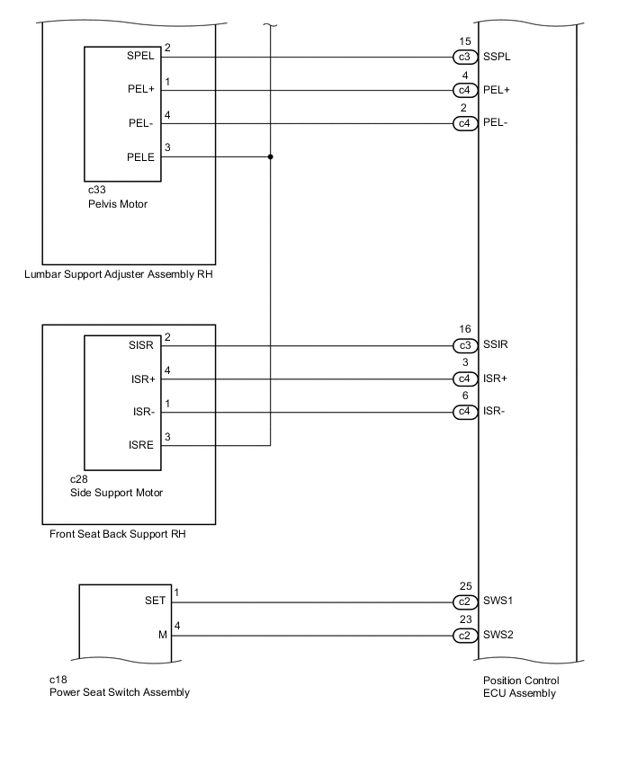
WIRING DIAGRAM
-
for Driver Side (Standard Seat Type):
-
for Driver Side (Sports Seat Type):
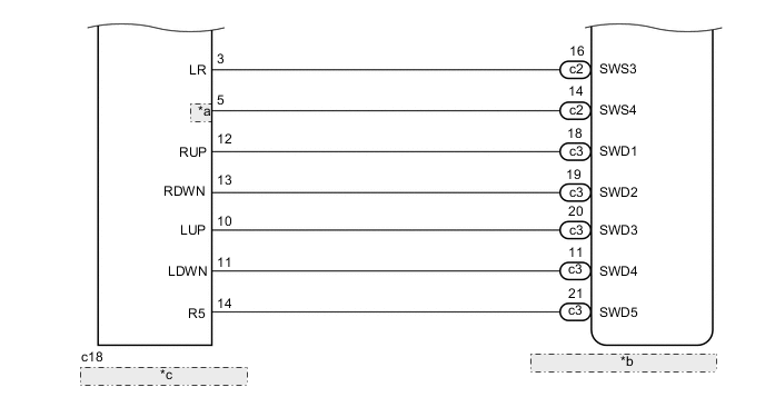
*a LF *b Position Control ECU Assembly *c Power Seat Switch Assembly -
for Driver Side (Luxury Seat Type):
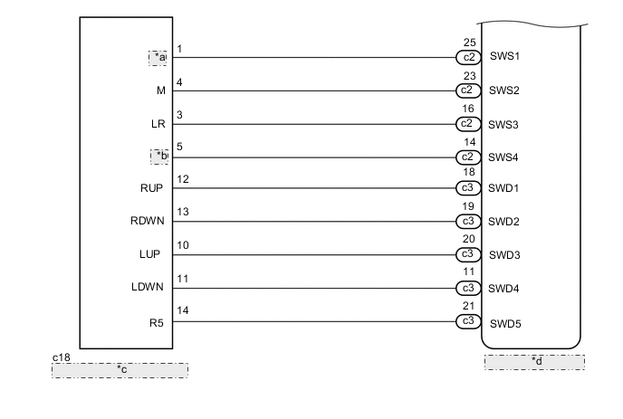
*a SET *b LF *c Power Seat Switch Assembly *d Position Control ECU Assembly -
for Front Passenger Side (Luxury Seat Type):
PROCEDURE
-
FRONT POWER SEAT CONTROL SYSTEM
-
Check which power seat functions are malfunctioning.
Result Result Proceed to One or more driver side power seat functions do not operate (for Standard Seat Type) A One or more driver side power seat functions do not operate (for Sports Seat Type) B One or more driver side power seat functions do not operate (for Luxury Seat Type) C One or more front passenger side power seat functions do not operate (for Luxury Seat Type) D All power seat functions do not operate E
B 
CHECK POWER SEAT FUNCTION Click here
C
CHECK POWER SEAT FUNCTION Click here
D
CHECK POWER SEAT FUNCTION Click here
E 
GO TO OTHER FLOW CHART (Front Power Seat does not Operate with Front Power Seat Switch) Click here
A 
-
-
CHECK POWER SEAT FUNCTION
-
Check that each function of the power seat operates normally by using the power seat switch Click here.
Result Result Proceed to Slide, front vertical and lifter functions does not operate A Reclining function does not operate B Lumbar support adjustment function does not operate C
B
READ VALUE USING GTS (RECLINING) Click here
C
INSPECT LUMBAR SUPPORT ADJUSTER ASSEMBLY RH (LUMBAR MOTOR) Click here
A
-
-
READ VALUE USING GTS
-
Connect the GTS to the DLC3.
-
Turn the power switch on (IG).
-
Turn the GTS on.
-
Enter the following menus: Body Electrical / Driver Seat / Data List.
-
Read the Data List according to the display on the GTS.
Driver Seat Tester Display Measurement item/Range Normal Condition Diagnostic Note Front Vertical Down Front vertical switch signal (Downward) / ON or OFF ON: Front vertical switch (Downward) on
OFF: Front vertical switch (Downward) off
- Front Vertical Up Front vertical switch signal (Upward) / ON or OFF ON: Front vertical switch (Upward) on
OFF: Front vertical switch (Upward) off
- Lifter Switch Down Lifter switch signal (Downward) / ON or OFF ON: Lifter switch (Downward) on
OFF: Lifter switch (Downward) off
- Lifter Switch Up Lifter switch signal (Upward) / ON or OFF ON: Lifter switch (Upward) on
OFF: Lifter switch (Upward) off
- Slide Rear Sliding switch signal (Rearward) / ON or OFF ON: Sliding switch (Rearward) on
OFF: Sliding switch (Rearward) off
- Slide Front Sliding switch signal (Forward) / ON or OFF ON: Sliding switch (Forward) on
OFF: Sliding switch (Forward) off
- OK ON or OFF is displayed on the GTS according to the table above.
NG
REPLACE POWER SEAT SWITCH ASSEMBLY Click here
OK
-
-
INSPECT FRONT SEAT ADJUSTER ASSEMBLY RH
-
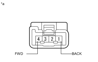
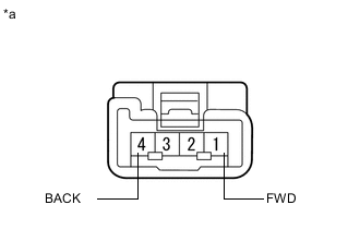
Text in Illustration *a Component without harness connected
(Front Seat Adjuster Assembly RH [Slide Motor])
Check the operation of the slide motor.
-
Disconnect the c6 front seat adjuster assembly RH connector.
-
Check if the slide motor moves smoothly when the battery is connected to the slide motor connector terminals.
OK Measurement Condition Operational Direction Battery positive (+) → 4 (FWD)
Battery negative (-) → 1 (BACK)
Forward Battery positive (+) → 1 (BACK)
Battery negative (-) → 4 (FWD)
Backward
-
-
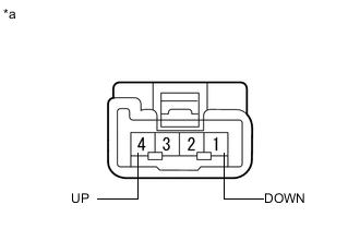
Text in Illustration *a Component without harness connected
(Front Seat Adjuster Assembly RH [Front Vertical Motor])
Check the operation of the front vertical motor.
-
Disconnect the c11 front seat adjuster assembly RH connector.
-
Check if the front vertical motor moves smoothly when the battery is connected to the front vertical motor connector terminals.
OK Measurement Condition Operational Direction Battery positive (+) → 4 (UP)
Battery negative (-) → 1 (DOWN)
Upward Battery positive (+) → 1 (DOWN)
Battery negative (-) → 4 (UP)
Downward
-
-
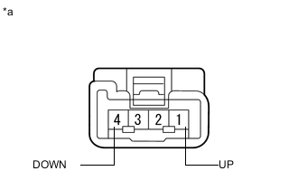
Text in Illustration *a Component without harness connected
(Front Seat Adjuster Assembly RH [Lifter Motor])
Check the operation of the lifter motor.
-
Disconnect the c13 front seat adjuster assembly RH connector.
-
Check if the lifter motor moves smoothly when the battery is connected to the lifter motor connector terminals.
OK Measurement Condition Operational Direction Battery positive (+) → 1 (UP)
Battery negative (-) → 4 (DOWN)
Upward Battery positive (+) → 4 (DOWN)
Battery negative (-) → 1 (UP)
Downward
-
NG
REPLACE FRONT SEAT ADJUSTER ASSEMBLY RH Click here
OK
-
-
CHECK HARNESS AND CONNECTOR (POWER SEAT SWITCH ASSEMBLY - FRONT SEAT ADJUSTER ASSEMBLY RH)
-
Disconnect the c15 and c17 power seat switch assembly connectors.
-
Disconnect the c6, c11 and c13 front seat adjuster assembly RH connectors.
-
Measure the resistance according to the value(s) in the table below.
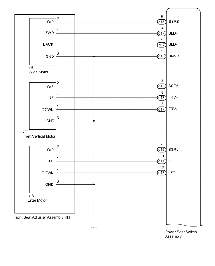
Standard Resistance Tester Connection Condition Specified Condition c15-5 (SSRS) - c6-2 (O/P) Always Below 1 Ω c17-3 (SLD+) - c6-4 (FWD) Always Below 1 Ω c17-4 (SLD-) - c6-1 (BACK) Always Below 1 Ω c15-1 (SGND) - c6-3 (GND) Always Below 1 Ω c15-3 (SSFV) - c11-2 (O/P) Always Below 1 Ω c17-8 (FRV+) - c11-4 (UP) Always Below 1 Ω c17-5 (FRV-) - c11-1 (DOWN) Always Below 1 Ω c15-1 (SGND) - c11-3 (GND) Always Below 1 Ω c15-4 (SSRL) - c13-2 (O/P) Always Below 1 Ω d15-10 (LFT+) - c13-1 (UP) Always Below 1 Ω d15-12 (LFT-) - c13-4 (DOWN) Always Below 1 Ω c15-1 (SGND) - c13-3 (GND) Always Below 1 Ω c15-5 (SSRS) - Body ground Always 10 kΩ or higher c17-3 (SLD+) - Body ground Always 10 kΩ or higher c17-4 (SLD-) - Body ground Always 10 kΩ or higher c15-1 (SGND) - Body ground Always 10 kΩ or higher c15-3 (SSFV) - Body ground Always 10 kΩ or higher c17-8 (FRV+) - Body ground Always 10 kΩ or higher c17-5 (FRV-) - Body ground Always 10 kΩ or higher c15-4 (SSRL) - Body ground Always 10 kΩ or higher c17-10 (LFT+) - Body ground Always 10 kΩ or higher c17-12 (LFT-) - Body ground Always 10 kΩ or higher
NG
REPAIR OR REPLACE HARNESS OR CONNECTOR
OK
-
-
CHECK POWER SEAT SWITCH ASSEMBLY
-
Temporarily replace the power seat switch assembly with a new or normally functioning one Click here.
-
Check the front power seat control system Click here.
OK Power seat operates normally
OK
END (POWER SEAT SWITCH ASSEMBLY WAS DEFECTIVE)
NG
REPLACE FRONT SEAT ADJUSTER ASSEMBLY RH Click here
-
-
READ VALUE USING GTS (RECLINING)
-
Connect the GTS to the DLC3.
-
Turn the power switch on (IG).
-
Turn the GTS on.
-
Enter the following menus: Body Electrical / Driver Seat / Data List.
-
Read the Data List according to the display on the GTS.
Driver Seat Tester Display Measurement item/Range Normal Condition Diagnostic Note Reclining Rear Reclining switch signal (Rearward) / ON or OFF ON: Reclining switch (Rearward) on
OFF: Reclining switch (Rearward) off
- Reclining Front Reclining switch signal (Forward) / ON or OFF ON: Reclining switch (Forward) on
OFF: Reclining switch (Forward) off
- OK ON or OFF is displayed on the GTS according to the table above.
NG
REPLACE POWER SEAT SWITCH ASSEMBLY Click here
OK
-
-
INSPECT POWER SEAT RECLINING MOTOR ASSEMBLY
-
Text in Illustration *a Component without harness connected
(Power Seat Reclining Motor Assembly)
Check the operation of the reclining motor.
-
Disconnect the c25 power seat reclining motor assembly connector.
-
Check if the reclining motor moves smoothly when the battery is connected to the reclining motor connector terminals.
OK Measurement Condition Operational Direction Battery positive (+) → 4 (FWD)
Battery negative (-) → 1 (BACK)
Forward Battery positive (+) → 1 (BACK)
Battery negative (-) → 4 (FWD)
Backward
-
NG
REPLACE POWER SEAT RECLINING MOTOR ASSEMBLY Click here
OK
-
-
CHECK HARNESS AND CONNECTOR (POWER SEAT SWITCH ASSEMBLY - POWER SEAT RECLINING MOTOR ASSEMBLY)
-
Disconnect the c15 and c17 power seat switch assembly connectors.
-
Disconnect the c25 power seat reclining motor assembly connector.
-
Measure the resistance according to the value(s) in the table below.
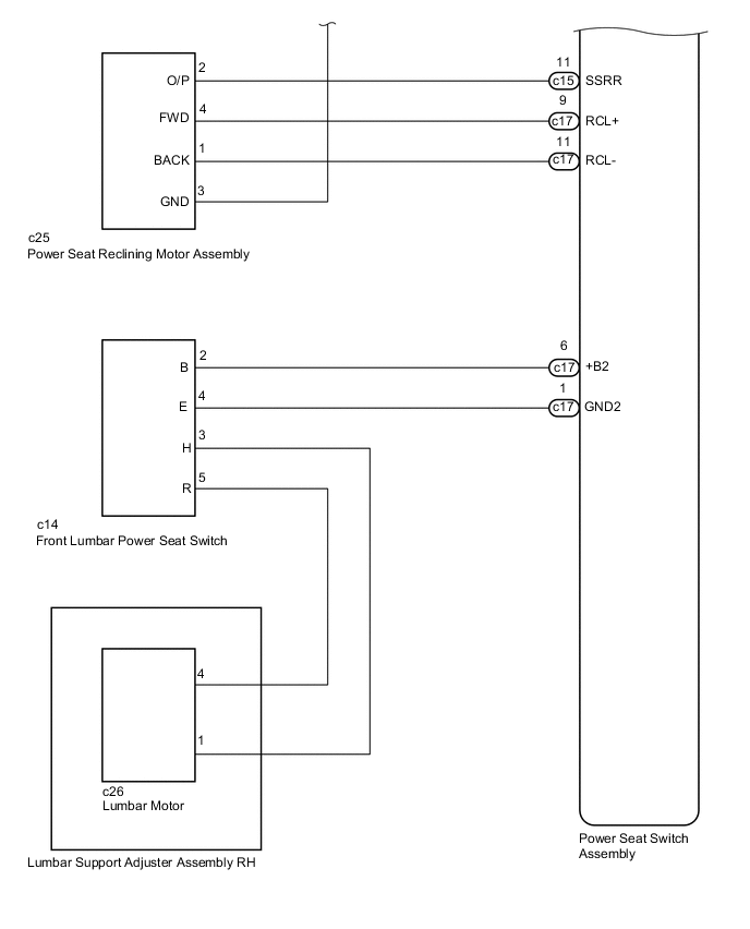
Standard Resistance Tester Connection Condition Specified Condition c15-11 (SSRR) - c25-2 (O/P) Always Below 1 Ω c17-9 (RCL+) - c25-4 (FWD) Always Below 1 Ω c17-11 (RCL-) - c25-1 (BACK) Always Below 1 Ω c15-1 (SGND) - c25-3 (GND) Always Below 1 Ω c15-11 (SSRR) - Body ground Always 10 kΩ or higher c17-11 (RCL+) - Body ground Always 10 kΩ or higher c17-9 (RCL-) - Body ground Always 10 kΩ or higher c15-1 (SGND) - Body ground Always 10 kΩ or higher
NG
REPAIR OR REPLACE HARNESS OR CONNECTOR
OK
-
-
CHECK POWER SEAT SWITCH ASSEMBLY
-
Temporarily replace the power seat switch assembly with a new or normally functioning one Click here.
-
Check the front power seat control system Click here.
OK Power seat operates normally
OK
END (POWER SEAT SWITCH ASSEMBLY WAS DEFECTIVE)
NG
REPLACE POWER SEAT RECLINING MOTOR ASSEMBLY Click here
-
-
INSPECT LUMBAR SUPPORT ADJUSTER ASSEMBLY RH (LUMBAR MOTOR)
-
Text in Illustration *a Component without harness connected
(Lumbar Support Adjuster Assembly RH [Lumbar Motor])
Check the operation of the lumbar motor.
-
Disconnect the c26 lumbar support adjuster assembly RH connector.
-
Check if the lumbar motor moves smoothly when the battery is connected to the lumbar motor connector terminals.
OK Measurement Condition Operational Direction Battery positive (+) → 1
Battery negative (-) → 4
Forward Battery positive (+) → 4
Battery negative (-) → 1
Backward
-
NG
REPLACE LUMBAR SUPPORT ADJUSTER ASSEMBLY RH (LUMBAR MOTOR) Click here
OK
-
-
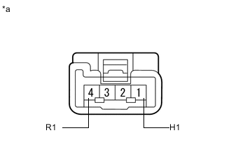
INSPECT FRONT LUMBAR POWER SEAT SWITCH
-
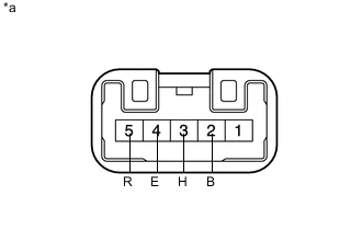
Text in Illustration *a Component without harness connected
(Front Lumbar Power Seat Switch)
Remove the front lumbar power seat switch Click here.
-
Measure the resistance according to the value(s) in the table below.
Standard Resistance Tester Connection Switch Condition Specified Condition 2 (B) - 3 (H) Hold Below 1 Ω 4 (E) - 5 (R) Off Below 1 Ω 3 (H) - 4 (E) Off Below 1 Ω 2 (B) - 5 (R) Release Below 1 Ω
NG
REPLACE FRONT LUMBAR POWER SEAT SWITCH Click here
OK
-
-
CHECK HARNESS AND CONNECTOR (POWER SEAT SWITCH ASSEMBLY - FRONT LUMBAR POWER SEAT SWITCH)
-
Disconnect the c17 power seat switch assembly connector.
-
Disconnect the c14 front lumbar power seat switch connector.
-
Measure the resistance according to the value(s) in the table below.
Standard Resistance Tester Connection Condition Specified Condition c17-6 (+B2) - c14-2 (B) Always Below 1 Ω c17-1 (GND2) - c14-4 (E) Always Below 1 Ω c17-6 (+B2) - Body ground Always 10 kΩ or higher c17-1 (GND2) - Body ground Always 10 kΩ or higher
NG
REPAIR OR REPLACE HARNESS OR CONNECTOR
OK
-
-
CHECK HARNESS AND CONNECTOR (LUMBAR SUPPORT ADJUSTER ASSEMBLY RH - FRONT LUMBAR POWER SEAT SWITCH)
-
Disconnect the c26 lumbar support adjuster assembly RH connector.
-
Disconnect the c14 front lumbar power seat switch connector.
-
Measure the resistance according to the value(s) in the table below.
Standard Resistance Tester Connection Condition Specified Condition c26-4 - c14-5 (R) Always Below 1 Ω c26-1 - c14-3 (H) Always Below 1 Ω c26-4 - Body ground Always 10 kΩ or higher c26-1 - Body ground Always 10 kΩ or higher
OK
REPLACE POWER SEAT SWITCH ASSEMBLY Click here
NG
REPAIR OR REPLACE HARNESS OR CONNECTOR
-
-
CHECK POWER SEAT FUNCTION
-
Check that each function of the power seat operates normally by using the power seat switch Click here.
Result Result Proceed to Slide, lifter, front vertical or cushion function does not operate A Reclining functions does not operate B Lumbar support adjustment or pelvis support function does not operate C Side support function does not operate D
B
PERFORM ACTIVE TEST USING GTS (SEAT RECLINING) Click here
C
PERFORM ACTIVE TEST USING GTS Click here
D
PERFORM ACTIVE TEST USING GTS (SIDE SUPPORT OPERATION) Click here
A
-
-
PERFORM ACTIVE TEST USING GTS
-
Connect the GTS to the DLC3.
-
Turn the power switch on (IG).
-
Turn the GTS on.
-
Enter the following menus: Body Electrical / Driver Seat / Active Test.
-
Perform the Active Test according to the display on the GTS.
Driver Seat Tester Display Test Part Control Range Seat Slide Operation Seat sliding operation Front / OFF / Rear Lifter Operation Seat lifter operation Up / OFF / Down Front Vertical Operation Seat front vertical operation Up / OFF / Down Cushion Length Seat cushion operation Front / OFF / Rear Result Result Proceed to Slide, lifter, front vertical and cushion functions operate normally A Slide, lifter, front vertical or cushion function does not operate B
B
INSPECT FRONT SEAT ADJUSTER ASSEMBLY RH Click here
A
-
-
CHECK HARNESS AND CONNECTOR (POSITION CONTROL ECU ASSEMBLY - POWER SEAT SWITCH ASSEMBLY)
-
Disconnect the c2 and c3 position control ECU assembly connectors.
-
Disconnect the c18 power seat switch assembly connector.
-
Measure the resistance according to the value(s) in the table below.
Standard Resistance Tester Connection Condition Specified Condition c2-25 (SWS1) - c18-1 (SET) Always Below 1 Ω c2-23 (SWS2) - c18-4 (M) Always Below 1 Ω c2-16 (SWS3) - c18-3 (LR) Always Below 1 Ω c2-14 (SWS4) - c18-5 (LF) Always Below 1 Ω c3-18 (SWD1) - c18-12 (RUP) Always Below 1 Ω c3-19 (SWD2) - c18-13 (RDWN) Always Below 1 Ω c3-20 (SWD3) - c18-10 (LUP) Always Below 1 Ω c3-11 (SWD4) - c18-11 (LDWN) Always Below 1 Ω c3-21 (SWD5) - c18-14 (R5) Always Below 1 Ω c2-25 (SWS1) - Body ground Always 10 kΩ or higher c2-23 (SWS2) - Body ground Always 10 kΩ or higher c2-16 (SWS3) - Body ground Always 10 kΩ or higher c2-14 (SWS4) - Body ground Always 10 kΩ or higher c3-18 (SWD1) - Body ground Always 10 kΩ or higher c3-19 (SWD2) - Body ground Always 10 kΩ or higher c3-20 (SWD3) - Body ground Always 10 kΩ or higher c3-11 (SWD4) - Body ground Always 10 kΩ or higher c3-21 (SWD5) - Body ground Always 10 kΩ or higher
NG
REPAIR OR REPLACE HARNESS OR CONNECTOR
OK
-
-
CHECK POWER SEAT SWITCH ASSEMBLY
-
Temporarily replace the power seat switch assembly with a new or normally functioning one Click here.
-
Check the front power seat control system Click here.
OK Power seat operates normally
OK
END (POWER SEAT SWITCH ASSEMBLY WAS DEFECTIVE)
NG
REPLACE POSITION CONTROL ECU ASSEMBLY Click here
-
-
INSPECT FRONT SEAT ADJUSTER ASSEMBLY RH
Tech Tips
Check the motor operation of applicable function.
-
Text in Illustration *a Component without harness connected
(Front Seat Adjuster Assembly RH [Slide Motor])
Check the operation of the slide motor.
-
Disconnect the c6 front seat adjuster assembly RH connector.
-
Check if the slide motor moves smoothly when the battery is connected to the slide motor connector terminals.
OK Measurement Condition Operational Direction Battery positive (+) → 4 (FWD)
Battery negative (-) → 1 (BACK)
Forward Battery positive (+) → 1 (BACK)
Battery negative (-) → 4 (FWD)
Backward
-
-
Text in Illustration *a Component without harness connected
(Front Seat Adjuster Assembly RH [Front Vertical Motor])
Check the operation of the front vertical motor.
-
Disconnect the c11 front seat adjuster assembly RH connector.
-
Check if the front vertical motor moves smoothly when the battery is connected to the front vertical motor connector terminals.
OK Measurement Condition Operational Direction Battery positive (+) → 4 (UP)
Battery negative (-) → 1 (DOWN)
Upward Battery positive (+) → 1 (DOWN)
Battery negative (-) → 4 (UP)
Downward
-
-
Text in Illustration *a Component without harness connected
(Front Seat Adjuster Assembly RH [Lifter Motor])
Check the operation of the lifter motor.
-
Disconnect the c13 front seat adjuster assembly RH connector.
-
Check if the lifter motor moves smoothly when the battery is connected to the lifter motor connector terminals.
OK Measurement Condition Operational Direction Battery positive (+) → 1 (UP)
Battery negative (-) → 4 (DOWN)
Upward Battery positive (+) → 4 (DOWN)
Battery negative (-) → 1 (UP)
Downward
-
-
Text in Illustration *a Component without harness connected
(Front Seat Adjuster Assembly RH [Cushion Motor])
Check the operation of the cushion motor.
-
Disconnect the c9 front seat adjuster assembly RH connector.
-
Check if the cushion motor moves smoothly when the battery is connected to the cushion motor connector terminals.
OK Measurement Condition Operational Direction Battery positive (+) → 1 (FWD)
Battery negative (-) → 4 (BACK)
Forward Battery positive (+) → 4 (BACK)
Battery negative (-) → 1 (FWD)
Backward
-
NG
REPLACE FRONT SEAT ADJUSTER ASSEMBLY RH Click here
OK
-
-
CHECK HARNESS AND CONNECTOR (POSITION CONTROL ECU ASSEMBLY - FRONT SEAT ADJUSTER ASSEMBLY RH)
-
Disconnect the c2, c3 and c5 position control ECU assembly connectors.
-
Disconnect the c6, c9, c11 and c13 front seat adjuster assembly RH connectors.
-
Measure the resistance according to the value(s) in the table below.
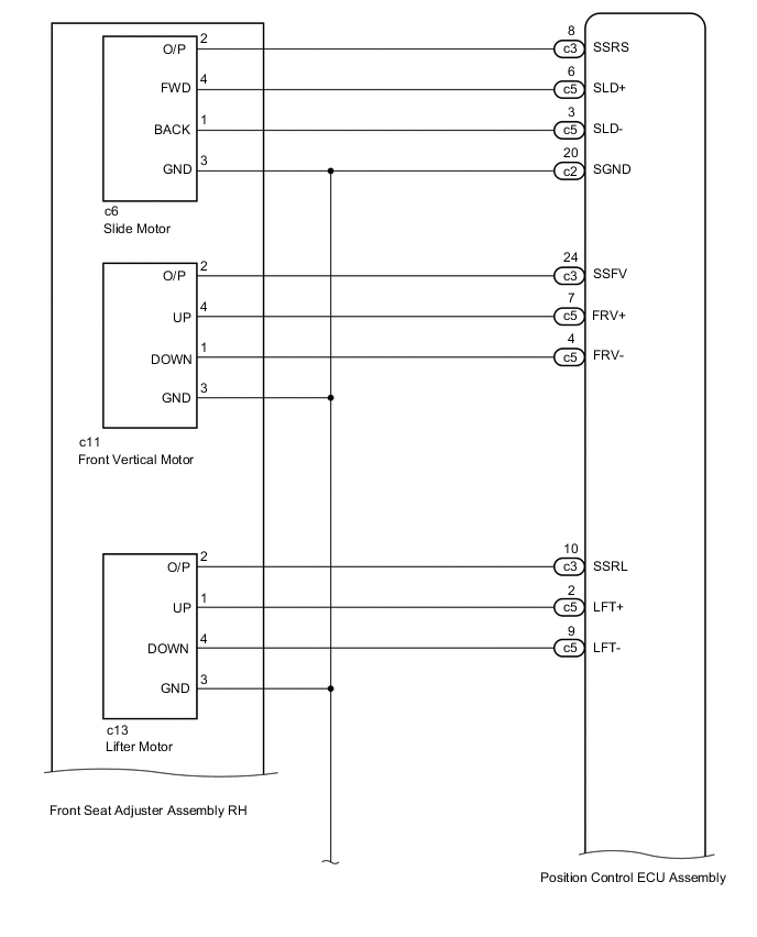
Standard Resistance Tester Connection Condition Specified Condition c3-8 (SSRS) - c6-2 (O/P) Always Below 1 Ω c5-6 (SLD+) - c6-4 (FWD) Always Below 1 Ω c5-3 (SLD-) - c6-1 (BACK) Always Below 1 Ω c2-20 (SGND) - c6-3 (GND) Always Below 1 Ω c3-24 (SSFV) - c11-2 (O/P) Always Below 1 Ω c5-7 (FRV+) - c11-4 (UP) Always Below 1 Ω c5-4 (FRV-) - c11-1 (DOWN) Always Below 1 Ω c2-20 (SGND) - c11-3 (GND) Always Below 1 Ω c3-10 (SSRL) - c13-2 (O/P) Always Below 1 Ω c5-2 (LFT+) - c13-1 (UP) Always Below 1 Ω c5-9 (LFT-) - c13-4 (DOWN) Always Below 1 Ω c2-20 (SGND) - c13-3 (GND) Always Below 1 Ω c3-3 (SSRC) - c9-2 (VCC) Always Below 1 Ω c3-6 (C+) - c9-1 (FWD) Always Below 1 Ω c2-4 (C-) - c9-4 (BACK) Always Below 1 Ω c2-20 (SGND) - c9-3 (GND) Always Below 1 Ω c3-8 (SSRS) - Body ground Always 10 kΩ or higher c5-6 (SLD+) - Body ground Always 10 kΩ or higher c5-3 (SLD-) - Body ground Always 10 kΩ or higher c2-20 (SGND) - Body ground Always 10 kΩ or higher c3-24 (SSFV) - Body ground Always 10 kΩ or higher c5-7 (FRV+) - Body ground Always 10 kΩ or higher c5-4 (FRV-) - Body ground Always 10 kΩ or higher c3-10 (SSRL) - Body ground Always 10 kΩ or higher c5-2 (LFT+) - Body ground Always 10 kΩ or higher c5-9 (LFT-) - Body ground Always 10 kΩ or higher c3-3 (SSRL) - Body ground Always 10 kΩ or higher c3-6 (C+) - Body ground Always 10 kΩ or higher c2-4 (C-) - Body ground Always 10 kΩ or higher
OK
REPLACE POSITION CONTROL ECU ASSEMBLY Click here
NG
REPAIR OR REPLACE HARNESS OR CONNECTOR
-
-
PERFORM ACTIVE TEST USING GTS (SEAT RECLINING)
-
Connect the GTS to the DLC3.
-
Turn the power switch on (IG).
-
Turn the GTS on.
-
Enter the following menus: Body Electrical / Driver Seat / Active Test.
-
Perform the Active Test according to the display on the GTS.
Driver Seat Tester Display Test Part Control Range Seat Reclining Seat reclining operation Front / OFF / Rear Result Result Proceed to Reclining function operate normally A Reclining function does not operate B
B
INSPECT POWER SEAT RECLINING MOTOR ASSEMBLY Click here
A
-
-
CHECK HARNESS AND CONNECTOR (POSITION CONTROL ECU ASSEMBLY - POWER SEAT SWITCH ASSEMBLY)
-
Disconnect the c2 and c3 position control ECU assembly connectors.
-
Disconnect the c18 power seat switch assembly connector.
-
Measure the resistance according to the value(s) in the table below.
Standard Resistance Tester Connection Condition Specified Condition c2-25 (SWS1) - c18-1 (SET) Always Below 1 Ω c3-20 (SWD3) - c18-10 (LUP) Always Below 1 Ω c3-11 (SWD4) - c18-11 (LDWN) Always Below 1 Ω c2-25 (SWS1) - Body ground Always 10 kΩ or higher c3-20 (SWD3) - Body ground Always 10 kΩ or higher c3-11 (SWD4) - Body ground Always 10 kΩ or higher
NG
REPAIR OR REPLACE HARNESS OR CONNECTOR
OK
-
-
CHECK POWER SEAT SWITCH ASSEMBLY
-
Temporarily replace the power seat switch assembly with a new or normally functioning one Click here.
-
Check the front power seat control system Click here.
OK Power seat operates normally
OK
END (POWER SEAT SWITCH ASSEMBLY WAS DEFECTIVE)
NG
REPLACE POSITION CONTROL ECU ASSEMBLY Click here
-
-
INSPECT POWER SEAT RECLINING MOTOR ASSEMBLY
-
Text in Illustration *a Component without harness connected
(Power Seat Reclining Motor Assembly)
Check the operation of the reclining motor.
-
Disconnect the c25 power seat reclining motor assembly connector.
-
Check if the reclining motor moves smoothly when the battery is connected to the reclining motor connector terminals.
OK Measurement Condition Operational Direction Battery positive (+) → 4 (FWD)
Battery negative (-) → 1 (BACK)
Forward Battery positive (+) → 1 (BACK)
Battery negative (-) → 4 (FWD)
Backward
-
NG
REPLACE POWER SEAT RECLINING MOTOR ASSEMBLY Click here
OK
-
-
CHECK HARNESS AND CONNECTOR (POSITION CONTROL ECU ASSEMBLY - POWER SEAT RECLINING MOTOR ASSEMBLY)
-
Disconnect the c2, c3 and c5 position control ECU assembly connectors.
-
Disconnect the c25 power seat reclining motor assembly connector.
-
Measure the resistance according to the value(s) in the table below.
Standard Resistance Tester Connection Condition Specified Condition c3-14 (SSRR) - c25-2 (O/P) Always Below 1 Ω c5-8 (RCL+) - c25-4 (FWD) Always Below 1 Ω c5-10 (RCL-) - c25-1 (BACK) Always Below 1 Ω c2-20 (SGND) - c25-3 (GND) Always Below 1 Ω c3-14 (SSRR) - Body ground Always 10 kΩ or higher c5-8 (RCL+) - Body ground Always 10 kΩ or higher c5-10 (RCL-) - Body ground Always 10 kΩ or higher c2-20 (SGND) - Body ground Always 10 kΩ or higher
OK
REPLACE POSITION CONTROL ECU ASSEMBLY Click here
NG
REPAIR OR REPLACE HARNESS OR CONNECTOR
-
-
PERFORM ACTIVE TEST USING GTS
-
Connect the GTS to the DLC3.
-
Turn the power switch on (IG).
-
Turn the GTS on.
-
Enter the following menus: Body Electrical / Driver Seat / Active Test.
-
Perform the Active Test according to the display on the GTS.
Driver Seat Tester Display Test Part Control Range Lumbar Slide Seat lumbar operation Front / OFF / Rear Pelvis Support Operation Seat pelvis operation Front / OFF / Rear Result Result Proceed to Lumbar support adjustment and pelvis functions operate normally A Lumbar support adjustment or pelvis function does not operate B
B
INSPECT LUMBAR SUPPORT ADJUSTER ASSEMBLY RH Click here
A
-
-
CHECK HARNESS AND CONNECTOR (POSITION CONTROL ECU ASSEMBLY - POWER SEAT SWITCH ASSEMBLY)
-
Disconnect the c2 and c3 position control ECU assembly connectors.
-
Disconnect the c18 power seat switch assembly connector.
-
Measure the resistance according to the value(s) in the table below.
Standard Resistance Tester Connection Condition Specified Condition c2-16 (SWS3) - c18-3 (LR) Always Below 1 Ω c3-18 (SWD1) - c18-12 (RUP) Always Below 1 Ω c3-19 (SWD2) - c18-13 (RDWN) Always Below 1 Ω c3-20 (SWD3) - c18-10 (LUP) Always Below 1 Ω c3-11 (SWD4) - c18-11 (LDWN) Always Below 1 Ω c2-16 (SWS3) - Body ground Always 10 kΩ or higher c3-18 (SWD1) - Body ground Always 10 kΩ or higher c3-19 (SWD2) - Body ground Always 10 kΩ or higher c3-20 (SWD3) - Body ground Always 10 kΩ or higher c3-11 (SWD4) - Body ground Always 10 kΩ or higher
NG
REPAIR OR REPLACE HARNESS OR CONNECTOR
OK
-
-
CHECK POWER SEAT SWITCH ASSEMBLY
-
Temporarily replace the power seat switch assembly with a new or normally functioning one Click here.
-
Check the front power seat control system Click here.
OK Power seat operates normally
OK
END (POWER SEAT SWITCH ASSEMBLY WAS DEFECTIVE)
NG
REPLACE POSITION CONTROL ECU ASSEMBLY Click here
-
-
INSPECT LUMBAR SUPPORT ADJUSTER ASSEMBLY RH
Tech Tips
Check the motor operation of applicable function.
-
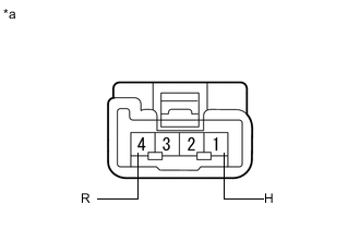
Text in Illustration *a Component without harness connected
(Lumbar Support Adjuster Assembly RH [Lumbar Motor])
Check the operation of the lumbar motor.
-
Disconnect the c26 lumbar support adjuster assembly RH connector.
-
Check if the lumbar motor moves smoothly when the battery is connected to the lumbar motor connector terminals.
OK Measurement Condition Operational Direction Battery positive (+) → 1 (H)
Battery negative (-) → 4 (R)
Forward Battery positive (+) → 4 (R)
Battery negative (-) → 1 (H)
Backward
-
-
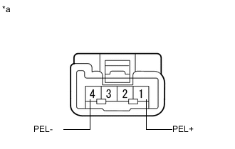
Text in Illustration *a Component without harness connected
(Lumbar Support Adjuster Assembly RH [Pelvis Motor])
Check the operation of the pelvis motor.
-
Disconnect the c33 lumbar support adjuster assembly RH connector.
-
Check if the pelvis motor moves smoothly when the battery is connected to the pelvis motor connector terminals.
OK Measurement Condition Operational Direction Battery positive (+) → 1 (PEL+)
Battery negative (-) → 4 (PEL-)
Forward Battery positive (+) → 4 (PEL-)
Battery negative (-) → 1 (PEL+)
Backward
-
NG
REPLACE LUMBAR SUPPORT ADJUSTER ASSEMBLY RH Click here
OK
-
-
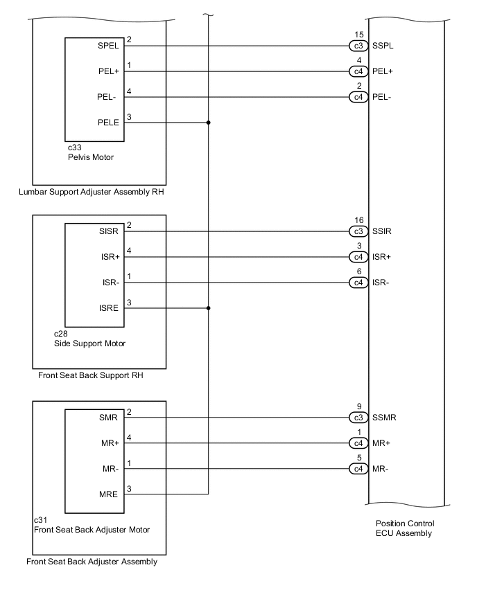
CHECK HARNESS AND CONNECTOR (POSITION CONTROL ECU ASSEMBLY - LUMBAR SUPPORT ADJUSTER ASSEMBLY RH)
-
Disconnect the c2, c3 and c4 position control ECU assembly connectors.
-
Disconnect the c26 and c33 lumbar support adjuster assembly RH connectors.
-
Measure the resistance according to the value(s) in the table below.
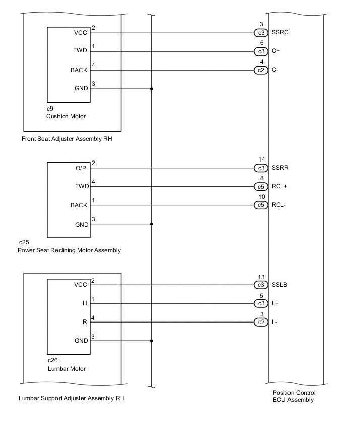
Standard Resistance Tester Connection Condition Specified Condition c3-13 (SSLB) - c26-2 (VCC) Always Below 1 Ω c3-5 (L+) - c26-1 (H) Always Below 1 Ω c2-3 (L-) - c26-4 (R) Always Below 1 Ω c2-20 (SGND) - c26-3 (GND) Always Below 1 Ω c3-15 (SSPL) - c33-2 (SPEL) Always Below 1 Ω c4-4 (PEL+) - c33-1 (PEL+) Always Below 1 Ω c4-2 (PEL-) - c33-4 (PEL-) Always Below 1 Ω c2-20 (SGND) - c33-3 (PELE) Always Below 1 Ω c3-13 (SSLB) - Body ground Always 10 kΩ or higher c3-5 (L+) - Body ground Always 10 kΩ or higher c2-3 (L-) - Body ground Always 10 kΩ or higher c2-20 (SGND) - Body ground Always 10 kΩ or higher c3-15 (SSPL) - Body ground Always 10 kΩ or higher c4-4 (PEL+) - Body ground Always 10 kΩ or higher c4-2 (PEL-) - Body ground Always 10 kΩ or higher
OK
REPLACE POSITION CONTROL ECU ASSEMBLY Click here
NG
REPAIR OR REPLACE HARNESS OR CONNECTOR
-
-
PERFORM ACTIVE TEST USING GTS (SIDE SUPPORT OPERATION)
-
Connect the GTS to the DLC3.
-
Turn the power switch on (IG).
-
Turn the GTS on.
-
Enter the following menus: Body Electrical / Driver Seat / Active Test.
-
Perform the Active Test according to the display on the GTS.
Driver Seat Tester Display Test Part Control Range Side Support Operation Seat side support operation Open / OFF / Close Result Result Proceed to Side support function operate normally A Side support function does not operate B
B
INSPECT FRONT SEAT BACK SUPPORT RH Click here
A
-
-
CHECK HARNESS AND CONNECTOR (POSITION CONTROL ECU ASSEMBLY - POWER SEAT SWITCH ASSEMBLY)
-
Disconnect the c2 and c3 position control ECU assembly connectors.
-
Disconnect the c18 power seat switch assembly connector.
-
Measure the resistance according to the value(s) in the table below.
Standard Resistance Tester Connection Condition Specified Condition c2-25 (SWS1) - c18-1 (SET) Always Below 1 Ω c2-23 (SWS2) - c18-4 (M) Always Below 1 Ω c3-21 (SWD5) - c18-14 (R5) Always Below 1 Ω c2-25 (SWS1) - Body ground Always 10 kΩ or higher c2-23 (SWS2) - Body ground Always 10 kΩ or higher c3-21 (SWD5) - Body ground Always 10 kΩ or higher
NG
REPAIR OR REPLACE HARNESS OR CONNECTOR
OK
-
-
CHECK POWER SEAT SWITCH ASSEMBLY
-
Temporarily replace the power seat switch assembly with a new or normally functioning one Click here.
-
Check the front power seat control system Click here.
OK Power seat operates normally
OK
END (POWER SEAT SWITCH ASSEMBLY WAS DEFECTIVE)
NG
REPLACE POSITION CONTROL ECU ASSEMBLY Click here
-
-
INSPECT FRONT SEAT BACK SUPPORT RH
-
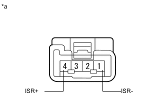
Text in Illustration *a Component without harness connected
(Front Seat Back Support RH [Side Support Motor])
Check the operation of the side support motor.
-
Disconnect the c28 front seat back support RH connector.
-
Check if the side support motor moves smoothly when the battery is connected to the side support motor connector terminals.
OK Measurement Condition Operational Direction Battery positive (+) → 4 (ISR+)
Battery negative (-) → 1 (ISR-)
Paddle Open Battery positive (+) → 1 (ISR-)
Battery negative (-) → 4 (ISR+)
Paddle Close
-
NG
REPLACE FRONT SEAT BACK SUPPORT RH Click here
OK
-
-
CHECK HARNESS AND CONNECTOR (POSITION CONTROL ECU ASSEMBLY - FRONT SEAT BACK SUPPORT RH)
-
Disconnect the c2, c3 and c4 position control ECU connectors.
-
Disconnect the c28 front seat back support RH connector.
-
Measure the resistance according to the value(s) in the table below.
Standard Resistance Tester Connection Condition Specified Condition c3-16 (SSIR) - c28-2 (SISR) Always Below 1 Ω c4-3 (ISR+) - c28-4 (ISR+) Always Below 1 Ω c4-6 (ISR-) - c28-1 (ISR-) Always Below 1 Ω c2-20 (SGND) - c28-3 (ISRE) Always Below 1 Ω c3-16 (SSIR) - Body ground Always 10 kΩ or higher c4-3 (ISR+) - Body ground Always 10 kΩ or higher c4-6 (ISR-) - Body ground Always 10 kΩ or higher c2-20 (SGND) - Body ground Always 10 kΩ or higher
OK
REPLACE POSITION CONTROL ECU ASSEMBLY Click here
NG
REPAIR OR REPLACE HARNESS OR CONNECTOR
-
-
CHECK POWER SEAT FUNCTION
-
Check that each function of the power seat operates normally by using the power seat switch Click here.
Result Result Proceed to Sliding, front vertical, lifter or cushion function does not operate A Reclining functions does not operate B Lumbar or pelvis function does not operate C Side support function does not operate D Front seat back adjuster function does not operate E
B
PERFORM ACTIVE TEST USING GTS (SEAT RECLINING) Click here
C
PERFORM ACTIVE TEST USING GTS Click here
D
PERFORM ACTIVE TEST USING GTS (SIDE SUPPORT OPERATION) Click here
E
PERFORM ACTIVE TEST USING GTS (REAR SEAT LUMBAR ADJUSTMENT) Click here
A
-
-
PERFORM ACTIVE TEST USING GTS
-
Connect the GTS to the DLC3.
-
Turn the power switch on (IG).
-
Turn the GTS on.
-
Enter the following menus: Body Electrical / Driver Seat / Active Test.
-
Perform the Active Test according to the display on the GTS.
Driver Seat Tester Display Test Part Control Range Seat Slide Operation Seat sliding operation Front / OFF / Rear Front Vertical Operation Seat front vertical operation Up / OFF / Down Lifter Operation Seat lifter operation Up / OFF / Down Cushion Length Seat cushion operation Front / OFF / Rear Result Result Proceed to Sliding, front vertical, lifter and cushion functions operate normally A Sliding, front vertical, lifter or cushion function does not operate B
B
INSPECT FRONT SEAT ADJUSTER ASSEMBLY RH Click here
A
-
-
CHECK HARNESS AND CONNECTOR (POSITION CONTROL ECU ASSEMBLY - POWER SEAT SWITCH ASSEMBLY)
-
Disconnect the c2 and c3 position control ECU assembly connectors.
-
Disconnect the c18 power seat switch assembly connector.
-
Measure the resistance according to the value(s) in the table below.
Standard Resistance Tester Connection Condition Specified Condition c2-25 (SWS1) - c18-1 (SET) Always Below 1 Ω c2-23 (SWS2) - c18-4 (M) Always Below 1 Ω c2-14 (SWS4) - c18-5 (LF) Always Below 1 Ω c3-18 (SWD1) - c18-12 (RUP) Always Below 1 Ω c3-19 (SWD2) - c18-13 (RDWN) Always Below 1 Ω c3-20 (SWD3) - c18-10 (LUP) Always Below 1 Ω c3-11 (SWD4) - c18-11 (LDWN) Always Below 1 Ω c2-25 (SWS1) - Body ground Always 10 kΩ or higher c2-23 (SWS2) - Body ground Always 10 kΩ or higher c2-14 (SWS4) - Body ground Always 10 kΩ or higher c3-18 (SWD1) - Body ground Always 10 kΩ or higher c3-19 (SWD2) - Body ground Always 10 kΩ or higher c3-20 (SWD3) - Body ground Always 10 kΩ or higher c3-11 (SWD4) - Body ground Always 10 kΩ or higher
NG
REPAIR OR REPLACE HARNESS OR CONNECTOR
OK
-
-
CHECK POWER SEAT SWITCH ASSEMBLY
-
Temporarily replace the power seat switch assembly with a new or normally functioning one Click here.
-
Check the front power seat control system Click here.
OK Power seat operates normally
OK
END (POWER SEAT SWITCH ASSEMBLY WAS DEFECTIVE)
NG
REPLACE POSITION CONTROL ECU ASSEMBLY Click here
-
-
INSPECT FRONT SEAT ADJUSTER ASSEMBLY RH
Tech Tips
Check the motor operation of applicable function.
-
Text in Illustration *a Component without harness connected
(Front Seat Adjuster Assembly RH [Slide Motor])
Check the operation of the slide motor.
-
Disconnect the c6 front seat adjuster assembly RH connector.
-
Check if the slide motor moves smoothly when the battery is connected to the slide motor connector terminals.
OK Measurement Condition Operational Direction Battery positive (+) → 4 (FWD)
Battery negative (-) → 1 (BACK)
Forward Battery positive (+) → 1 (BACK)
Battery negative (-) → 4 (FWD)
Backward
-
-
Text in Illustration *a Component without harness connected
(Front Seat Adjuster Assembly RH [Front Vertical Motor])
Check the operation of the front vertical motor.
-
Disconnect the c11 front seat adjuster assembly RH connector.
-
Check if the front vertical motor moves smoothly when the battery is connected to the front vertical motor connector terminals.
OK Measurement Condition Operational Direction Battery positive (+) → 4 (UP)
Battery negative (-) → 1 (DOWN)
Upward Battery positive (+) → 1 (DOWN)
Battery negative (-) → 4 (UP)
Downward
-
-
Text in Illustration *a Component without harness connected
(Front Seat Adjuster Assembly RH [Lifter Motor])
Check the operation of the lifter motor.
-
Disconnect the c13 front seat adjuster assembly RH connector.
-
Check if the lifter motor moves smoothly when the battery is connected to the lifter motor connector terminals.
OK Measurement Condition Operational Direction Battery positive (+) → 1 (UP)
Battery negative (-) → 4 (DOWN)
Upward Battery positive (+) → 4 (DOWN)
Battery negative (-) → 1 (UP)
Downward
-
-
Text in Illustration *a Component without harness connected
(Front Seat Adjuster Assembly RH [Cushion Motor])
Check the operation of the cushion motor.
-
Disconnect the c9 front seat adjuster assembly RH connector.
-
Check if the cushion motor moves smoothly when the battery is connected to the cushion motor connector terminals.
OK Measurement Condition Operational Direction Battery positive (+) → 1 (FWD)
Battery negative (-) → 4 (BACK)
Forward Battery positive (+) → 4 (BACK)
Battery negative (-) → 1 (FWD)
Backward
-
NG
REPLACE FRONT SEAT ADJUSTER ASSEMBLY RH Click here
OK
-
-
CHECK HARNESS AND CONNECTOR (POSITION CONTROL ECU ASSEMBLY - FRONT SEAT ADJUSTER ASSEMBLY RH)
-
Disconnect the c2, c3 and c5 position control ECU assembly connectors.
-
Disconnect the c6, c9, c11 and c13 front seat adjuster assembly connectors.
-
Measure the resistance according to the value(s) in the table below.
Standard Resistance Tester Connection Condition Specified Condition c3-8 (SSRS) - c6-2 (O/P) Always Below 1 Ω c5-6 (SLD+) - c6-4 (FWD) Always Below 1 Ω c5-3 (SLD-) - c6-1 (BACK) Always Below 1 Ω c2-20 (SGND) - c6-3 (GND) Always Below 1 Ω c3-24 (SSFV) - c11-2 (O/P) Always Below 1 Ω c5-7 (FRV+) - c11-4 (UP) Always Below 1 Ω c5-4 (FRV-) - c11-1 (DOWN) Always Below 1 Ω c2-20 (SGND) - c11-3 (GND) Always Below 1 Ω c3-10 (SSRL) - c13-2 (O/P) Always Below 1 Ω c5-2 (LFT+) - c13-1 (UP) Always Below 1 Ω c5-9 (LFT-) - c13-4 (DOWN) Always Below 1 Ω c2-20 (SGND) - c13-3 (GND) Always Below 1 Ω c3-3 (SSRC) - c9-2 (VCC) Always Below 1 Ω c3-6 (C+) - c9-1 (FWD) Always Below 1 Ω c2-4 (C-) - c9-4 (BACK) Always Below 1 Ω c2-20 (SGND) - c9-3 (GND) Always Below 1 Ω c3-8 (SSRS) - Body ground Always 10 kΩ or higher c5-6 (SLD+) - Body ground Always 10 kΩ or higher c5-3 (SLD-) - Body ground Always 10 kΩ or higher c2-20 (SGND) - Body ground Always 10 kΩ or higher c3-24 (SSFV) - Body ground Always 10 kΩ or higher c5-7 (FRV+) - Body ground Always 10 kΩ or higher c5-4 (FRV-) - Body ground Always 10 kΩ or higher c3-10 (SSRL) - Body ground Always 10 kΩ or higher c5-2 (LFT+) - Body ground Always 10 kΩ or higher c5-9 (LFT-) - Body ground Always 10 kΩ or higher c3-3 (SSRC) - Body ground Always 10 kΩ or higher c3-6 (C+) - Body ground Always 10 kΩ or higher c2-4 (C-) - Body ground Always 10 kΩ or higher
OK
REPLACE POSITION CONTROL ECU ASSEMBLY Click here
NG
REPAIR OR REPLACE HARNESS OR CONNECTOR
-
-
PERFORM ACTIVE TEST USING GTS (SEAT RECLINING)
-
Connect the GTS to the DLC3.
-
Turn the power switch on (IG).
-
Turn the GTS on.
-
Enter the following menus: Body Electrical / Driver Seat / Active Test.
-
Perform the Active Test according to the display on the GTS.
Driver Seat Tester Display Test Part Control Range Seat Reclining Seat reclining operation Front / OFF / Rear Result Result Proceed to Reclining function operate normally A Reclining function does not operate B
B
INSPECT POWER SEAT RECLINING MOTOR ASSEMBLY Click here
A
-
-
CHECK HARNESS AND CONNECTOR (POSITION CONTROL ECU ASSEMBLY - POWER SEAT SWITCH ASSEMBLY)
-
Disconnect the c2 and c3 position control ECU assembly connectors.
-
Disconnect the c18 power seat switch assembly connector.
-
Measure the resistance according to the value(s) in the table below.
Standard Resistance Tester Connection Condition Specified Condition c2-25 (SWS1) - c18-1 (SET) Always Below 1 Ω c3-20 (SWD3) - c18-10 (LUP) Always Below 1 Ω c3-11 (SWD4) - c18-11 (LDWN) Always Below 1 Ω c2-25 (SWS1) - Body ground Always 10 kΩ or higher c3-20 (SWD3) - Body ground Always 10 kΩ or higher c3-11 (SWD4) - Body ground Always 10 kΩ or higher
NG
REPAIR OR REPLACE HARNESS OR CONNECTOR
OK
-
-
CHECK POWER SEAT SWITCH ASSEMBLY
-
Temporarily replace the power seat switch assembly with a new or normally functioning one Click here.
-
Check the front power seat control system Click here.
OK Power seat operates normally
OK
END (POWER SEAT SWITCH ASSEMBLY WAS DEFECTIVE)
NG
REPLACE POSITION CONTROL ECU ASSEMBLY Click here
-
-
INSPECT POWER SEAT RECLINING MOTOR ASSEMBLY
-
Text in Illustration *a Component without harness connected
(Power Seat Reclining Motor Assembly)
Check the operation of the reclining motor.
-
Disconnect the c25 power seat reclining motor assembly connector.
-
Check if the reclining motor moves smoothly when the battery is connected to the reclining motor connector terminals.
OK Measurement Condition Operational Direction Battery positive (+) → 4 (FWD)
Battery negative (-) → 1 (BACK)
Forward Battery positive (+) → 1 (BACK)
Battery negative (-) → 4 (FWD)
Backward
-
NG
REPLACE POWER SEAT RECLINING MOTOR ASSEMBLY Click here
OK
-
-
CHECK HARNESS AND CONNECTOR (POSITION CONTROL ECU ASSEMBLY - POWER SEAT RECLINING MOTOR ASSEMBLY)
-
Disconnect the c2, c3 and c5 position control ECU assembly connectors.
-
Disconnect the c25 power seat reclining motor assembly connector.
-
Measure the resistance according to the value(s) in the table below.
Standard Resistance Tester Connection Condition Specified Condition c3-14 (SSRR) - c25-2 (O/P) Always Below 1 Ω c5-8 (RCL+) - c25-4 (FWD) Always Below 1 Ω c5-10 (RCL-) - c25-1 (BACK) Always Below 1 Ω c2-20 (SGND) - c25-3 (GND) Always Below 1 Ω c3-14 (SSRR) - Body ground Always 10 kΩ or higher c5-8 (RCL+) - Body ground Always 10 kΩ or higher c5-10 (RCL-) - Body ground Always 10 kΩ or higher c2-20 (SGND) - Body ground Always 10 kΩ or higher
OK
REPLACE POSITION CONTROL ECU ASSEMBLY Click here
NG
REPAIR OR REPLACE HARNESS OR CONNECTOR
-
-
PERFORM ACTIVE TEST USING GTS
-
Connect the GTS to the DLC3.
-
Turn the power switch on (IG).
-
Turn the GTS on.
-
Enter the following menus: Body Electrical / Driver Seat / Active Test.
-
Perform the Active Test according to the display on the GTS.
Driver Seat Tester Display Test Part Control Range Lumbar Slide Seat lumbar operation Up / OFF / Down Pelvis Support Operation Seat pelvis operation Up / OFF / Down Result Result Proceed to Lumbar support adjustment and pelvis functions operate normally A Lumbar support adjustment or pelvis function does not operate B
B
INSPECT LUMBAR SUPPORT ADJUSTER ASSEMBLY RH Click here
A
-
-
CHECK HARNESS AND CONNECTOR (POSITION CONTROL ECU ASSEMBLY - POWER SEAT SWITCH ASSEMBLY)
-
Disconnect the c2 and c3 position control ECU assembly connectors.
-
Disconnect the c18 power seat switch assembly connector.
-
Measure the resistance according to the value(s) in the table below.
Standard Resistance Tester Connection Condition Specified Condition c2-16 (SWS3) - c18-3 (LR) Always Below 1 Ω c3-18 (SWD1) - c18-12 (RUP) Always Below 1 Ω c3-19 (SWD2) - c18-13 (RDWN) Always Below 1 Ω c3-20 (SWD3) - c18-10 (LUP) Always Below 1 Ω c3-11 (SWD4) - c18-11 (LDWN) Always Below 1 Ω c2-16 (SWS3) - Body ground Always 10 kΩ or higher c3-18 (SWD1) - Body ground Always 10 kΩ or higher c3-19 (SWD2) - Body ground Always 10 kΩ or higher c3-20 (SWD3) - Body ground Always 10 kΩ or higher c3-11 (SWD4) - Body ground Always 10 kΩ or higher
NG
REPAIR OR REPLACE HARNESS OR CONNECTOR
OK
-
-
CHECK POWER SEAT SWITCH ASSEMBLY
-
Temporarily replace the power seat switch assembly with a new or normally functioning one Click here.
-
Check the front power seat control system Click here.
OK Power seat operates normally
OK
END (POWER SEAT SWITCH ASSEMBLY WAS DEFECTIVE)
NG
REPLACE POSITION CONTROL ECU ASSEMBLY Click here
-
-
INSPECT LUMBAR SUPPORT ADJUSTER ASSEMBLY RH
Tech Tips
Check the motor operation of applicable function.
-

Text in Illustration *a Component without harness connected
(Lumbar Support Adjuster Assembly RH [Lumbar Motor])
Check the operation of the lumbar motor.
-
Disconnect the c26 lumbar support adjuster assembly RH connector.
-
Check if the lumbar motor moves smoothly when the battery is connected to the lumbar motor connector terminals.
OK Measurement Condition Specified Condition Battery positive (+) → 1 (H)
Battery negative (-) → 4 (R)
Forward Battery positive (+) → 4 (R)
Battery negative (-) → 1 (H)
Backward
-
-
Text in Illustration *a Component without harness connected
(Lumbar Support Adjuster Assembly RH [Pelvis Motor])
Check the operation of the pelvis motor.
-
Disconnect the c33 lumbar support adjuster assembly RH connector.
-
Check if the pelvis motor moves smoothly when the battery is connected to the pelvis motor connector terminals.
OK Measurement Condition Specified Condition Battery positive (+) → 1 (PEL+)
Battery negative (-) → 4 (PEL-)
Forward Battery positive (+) → 4 (PEL-)
Battery negative (-) → 1 (PEL+)
Backward
-
NG
REPLACE LUMBAR SUPPORT ADJUSTER ASSEMBLY RH Click here
OK
-
-
CHECK HARNESS AND CONNECTOR (POSITION CONTROL ECU ASSEMBLY - LUMBAR SUPPORT ADJUSTER ASSEMBLY RH)
-
Disconnect the c2, c3 and c4 position control ECU assembly connectors.
-
Disconnect the c26 and c33 lumbar support adjuster assembly RH connectors.
-
Measure the resistance according to the value(s) in the table below.
Standard Resistance Tester Connection Condition Specified Condition c3-13 (SSLB) - c26-2 (VCC) Always Below 1 Ω c3-5 (L+) - c26-1 (H) Always Below 1 Ω c2-3 (L-) - c26-4 (R) Always Below 1 Ω c2-20 (SGND) - c26-3 (GND) Always Below 1 Ω c3-15 (SSPL) - c33-2 (SPEL) Always Below 1 Ω c4-4 (PEL+) - c33-1 (PEL+) Always Below 1 Ω c4-2 (PEL-) - c33-4 (PEL-) Always Below 1 Ω c2-20 (SGND) - c33-3 (PELE) Always Below 1 Ω c3-13 (SSLB) - Body ground Always 10 kΩ or higher c3-5 (L+) - Body ground Always 10 kΩ or higher c2-3 (L-) - Body ground Always 10 kΩ or higher c2-20 (SGND) - Body ground Always 10 kΩ or higher c3-15 (SSPL) - Body ground Always 10 kΩ or higher c4-4 (PEL+) - Body ground Always 10 kΩ or higher c4-2 (PEL-) - Body ground Always 10 kΩ or higher
OK
REPLACE POSITION CONTROL ECU ASSEMBLY Click here
NG
REPAIR OR REPLACE HARNESS OR CONNECTOR
-
-
PERFORM ACTIVE TEST USING GTS (SIDE SUPPORT OPERATION)
-
Connect the GTS to the DLC3.
-
Turn the power switch on (IG).
-
Turn the GTS on.
-
Enter the following menus: Body Electrical / Driver Seat / Active Test.
-
Perform the Active Test according to the display on the GTS.
Driver Seat Tester Display Test Part Control Range Side Support Operation Seat side support operation Open / OFF / Close Result Result Proceed to Side support function operate normally A Side support function does not operate B
B
INSPECT FRONT SEAT BACK SUPPORT RH Click here
A
-
-
CHECK HARNESS AND CONNECTOR (POSITION CONTROL ECU ASSEMBLY - POWER SEAT SWITCH ASSEMBLY)
-
Disconnect the c2 and c3 position control ECU assembly connectors.
-
Disconnect the c18 power seat switch assembly connector.
-
Measure the resistance according to the value(s) in the table below.
Standard Resistance Tester Connection Condition Specified Condition c2-25 (SWS1) - c18-1 (SET) Always Below 1 Ω c2-23 (SWS2) - c18-4 (M) Always Below 1 Ω c3-21 (SWD5) - c18-14 (R5) Always Below 1 Ω c2-25 (SWS1) - Body ground Always 10 kΩ or higher c2-23 (SWS2) - Body ground Always 10 kΩ or higher c3-21 (SWD5) - Body ground Always 10 kΩ or higher
NG
REPAIR OR REPLACE HARNESS OR CONNECTOR
OK
-
-
CHECK POWER SEAT SWITCH ASSEMBLY
-
Temporarily replace the power seat switch assembly with a new or normally functioning one Click here.
-
Check the front power seat control system Click here.
OK Power seat operates normally
OK
END (POWER SEAT SWITCH ASSEMBLY WAS DEFECTIVE)
NG
REPLACE POSITION CONTROL ECU ASSEMBLY Click here
-
-
INSPECT FRONT SEAT BACK SUPPORT RH
-
Text in Illustration *a Component without harness connected
(Front Seat Back Support RH [Side Support Motor])
Check the operation of the side support motor.
-
Disconnect the c28 front seat back support RH connector.
-
Check if the side support motor moves smoothly when the battery is connected to the side support motor connector terminals.
OK Measurement Condition Operational Direction Battery positive (+) → 4 (ISR+)
Battery negative (-) → 1 (ISR-)
Paddle Open Battery positive (+) → 1 (ISR-)
Battery negative (-) → 4 (ISR+)
Paddle Close
-
NG
REPLACE FRONT SEAT BACK SUPPORT RH Click here
OK
-
-
CHECK HARNESS AND CONNECTOR (POSITION CONTROL ECU ASSEMBLY - FRONT SEAT BACK SUPPORT RH)
-
Disconnect the c2, c3 and c4 position control ECU assembly connectors.
-
Disconnect the c28 front seat back support RH connector.
-
Measure the resistance according to the value(s) in the table below.
Standard Resistance Tester Connection Condition Specified Condition c3-16 (SSIR) - c28-2 (SISR) Always Below 1 Ω c4-3 (ISR+) - c28-4 (ISR+) Always Below 1 Ω c4-6 (ISR-) - c28-1 (ISR-) Always Below 1 Ω c2-20 (SGND) - c28-3 (ISRE) Always Below 1 Ω c3-16 (SSIR) - Body ground Always 10 kΩ or higher c4-3 (ISR+) - Body ground Always 10 kΩ or higher c4-6 (ISR-) - Body ground Always 10 kΩ or higher c2-20 (SGND) - Body ground Always 10 kΩ or higher
OK
REPLACE POSITION CONTROL ECU ASSEMBLY Click here
NG
REPAIR OR REPLACE HARNESS OR CONNECTOR
-
-
PERFORM ACTIVE TEST USING GTS (REAR SEAT LUMBAR ADJUSTMENT)
-
Connect the GTS to the DLC3.
-
Turn the power switch on (IG).
-
Turn the GTS on.
-
Enter the following menus: Body Electrical / Driver Seat / Active Test.
-
Perform the Active Test according to the display on the GTS.
Driver Seat Tester Display Test Part Control Range Rear Seat Lumbar Adjustment Seat back support adjustment operation Up / OFF / Down Result Result Proceed to Front seat back adjustment function operate normally A Front seat back adjustment function does not operate B
B
INSPECT FRONT SEAT BACK ADJUSTER ASSEMBLY Click here
A
-
-
CHECK HARNESS AND CONNECTOR (POSITION CONTROL ECU ASSEMBLY - POWER SEAT SWITCH ASSEMBLY)
-
Disconnect the c2 and c3 position control ECU assembly connectors.
-
Disconnect the c18 power seat switch assembly connector.
-
Measure the resistance according to the value(s) in the table below.
Standard Resistance Tester Connection Condition Specified Condition c2-14 (SWS4) - c18-5 (LF) Always Below 1 Ω c3-18 (SWD1) - c18-12 (RUP) Always Below 1 Ω c3-19 (SWD2) - c18-13 (RDWN) Always Below 1 Ω c2-14 (SWS4) - Body ground Always 10 kΩ or higher c3-18 (SWD1) - Body ground Always 10 kΩ or higher c3-19 (SWD2) - Body ground Always 10 kΩ or higher
NG
REPAIR OR REPLACE HARNESS OR CONNECTOR
OK
-
-
CHECK POWER SEAT SWITCH ASSEMBLY
-
Temporarily replace the power seat switch assembly with a new or normally functioning one Click here.
-
Check the front power seat control system Click here.
OK Power seat operates normally
OK
END (POWER SEAT SWITCH ASSEMBLY WAS DEFECTIVE)
NG
REPLACE POSITION CONTROL ECU ASSEMBLY Click here
-
-
INSPECT FRONT SEAT BACK ADJUSTER ASSEMBLY
-

Text in Illustration *a Component without harness connected
(Front Seat Back Adjuster Assembly [Front Seat Back Adjuster Motor])
Check the operation of the front seat back adjuster motor.
-
Disconnect the c31 front seat back adjuster assembly connector.
-
Check if the front seat back adjuster motor moves smoothly when the battery is connected to the front seat back adjuster motor connector terminals.
OK Measurement Condition Operational Direction Battery positive (+) → 4 (MR+)
Battery negative (-) → 1 (MR-)
Forward Battery positive (+) → 1 (MR-)
Battery negative (-) → 4 (MR+)
Backward
-
NG
REPLACE FRONT SEAT BACK ADJUSTER ASSEMBLY Click here
OK
-
-
CHECK HARNESS AND CONNECTOR (POSITION CONTROL ECU ASSEMBLY - FRONT SEAT BACK ADJUSTER MOTOR)
-
Disconnect the c2, c3 and c4 position control ECU assembly connectors.
-
Disconnect the c31 front seat back adjuster assembly connector.
-
Measure the resistance according to the value(s) in the table below.
Standard Resistance Tester Connection Condition Specified Condition c3-9 (SSMR) - c31-2 (SMR) Always Below 1 Ω c4-1 (MR+) - c31-4 (MR+) Always Below 1 Ω c4-5 (MR-) - c31-1 (MR-) Always Below 1 Ω c2-20 (SGND) - c31-3 (MRE) Always Below 1 Ω c3-9 (SSMR) - Body ground Always 10 kΩ or higher c4-1 (MR+) - Body ground Always 10 kΩ or higher c4-5 (MR-) - Body ground Always 10 kΩ or higher c2-20 (SGND) - Body ground Always 10 kΩ or higher
OK
REPLACE POSITION CONTROL ECU ASSEMBLY Click here
NG
REPAIR OR REPLACE HARNESS OR CONNECTOR
-
-
CHECK POWER SEAT FUNCTION
-
Check that each function of the power seat operates normally by using the power seat switch Click here.
Result Result Proceed to Slide, front vertical, lifter, cushion*1 or ottoman*2 functions does not operate A Reclining functions does not operate B Lumbar support adjustment or pelvis function does not operate C Side support adjustment or front seat back adjustment function does not operate D
-
*1: except Ottoman
-
*2: for Ottoman
-
B
PERFORM ACTIVE TEST USING GTS (SEAT RECLINING) Click here
C
PERFORM ACTIVE TEST USING GTS Click here
D
PERFORM ACTIVE TEST USING GTS Click here
A
-
-
PERFORM ACTIVE TEST USING GTS
-
Connect the GTS to the DLC3.
-
Turn the power switch on (IG).
-
Turn the GTS on.
-
Enter the following menus: Body Electrical / Passenger Seat / Active Test.
-
Perform the Active Test according to the display on the GTS.
Passenger Seat Tester Display Test Part Control Range Seat Slide Operation Seat sliding operation Front / OFF / Rear Lifter Operation Seat lifter operation Up / OFF / Down Front Vertical Operation Seat front vertical operation Up / OFF / Down Cushion Length*1 Seat cushion operation Front / OFF / Rear Ottoman*2 Seat ottoman operation Up / OFF / Down
-
*1: except Ottoman
-
*2: for Ottoman
Result Result Proceed to Slide, front vertical, lifter cushion and ottoman functions operate normally A Slide, front vertical, lifter cushion or ottoman function does not operate B -
B
INSPECT FRONT SEAT ADJUSTER ASSEMBLY LH Click here
A
-
-
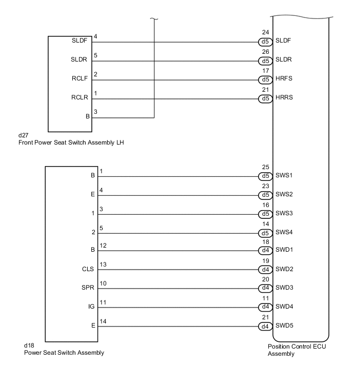
CHECK HARNESS AND CONNECTOR (POSITION CONTROL ECU ASSEMBLY - POWER SEAT SWITCH ASSEMBLY)
-
Disconnect the d4 and d5 position control ECU assembly connectors.
-
Disconnect the d18 power seat switch assembly connector.
-
Measure the resistance according to the value(s) in the table below.
Standard Resistance Tester Connection Condition Specified Condition d5-25 (SWS1) - d18-1 (B) Always Below 1 Ω d5-23 (SWS2) - d18-4 (E) Always Below 1 Ω d5-14 (SWS4) - d18-5 (2) Always Below 1 Ω d4-18 (SWD1) - d18-12 (B) Always Below 1 Ω d4-19 (SWD2) - d18-13 (CLS) Always Below 1 Ω d4-20 (SWD3) - d18-10 (SPR) Always Below 1 Ω d4-11 (SWD4) - d18-11 (IG) Always Below 1 Ω d5-25 (SWS1) - Body ground Always 10 kΩ or higher d5-23 (SWS2) - Body ground Always 10 kΩ or higher d5-14 (SWS4) - Body ground Always 10 kΩ or higher d4-18 (SWD1) - Body ground Always 10 kΩ or higher d4-19 (SWD2) - Body ground Always 10 kΩ or higher d4-20 (SWD3) - Body ground Always 10 kΩ or higher d4-11 (SWD4) - Body ground Always 10 kΩ or higher
NG
REPAIR OR REPLACE HARNESS OR CONNECTOR
OK
-
-
CHECK HARNESS AND CONNECTOR (POSITION CONTROL ECU ASSEMBLY - FRONT POWER SEAT SWITCH LH)
-
Disconnect the d5 position control ECU assembly connector.
-
Disconnect the d27 front power seat switch LH connector.
-
Measure the resistance according to the value(s) in the table below.
Standard Resistance Tester Connection Condition Specified Condition d5-24 (SLDF) - d27-4 (SLDF) Always Below 1 Ω d5-26 (SLDR) - d27-5 (SLDR) Always Below 1 Ω d5-20 (SGND) - d27-3 (B) Always Below 1 Ω d5-24 (SLDF) - Body ground Always 10 kΩ or higher d5-26 (SLDR) - Body ground Always 10 kΩ or higher d5-20 (SGND) - Body ground Always 10 kΩ or higher
NG
REPAIR OR REPLACE HARNESS OR CONNECTOR
OK
-
-
INSPECT FRONT POWER SEAT SWITCH ASSEMBLY LH
-
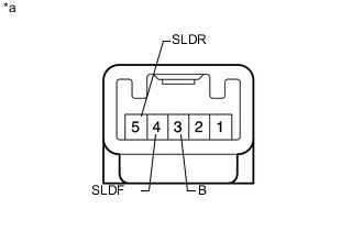
Text in Illustration *a Component without harness connected
(Front Power Seat Switch Assembly LH)
Remove the front power seat switch assembly LH Click here.
-
Measure the resistance according to the value(s) in the table below.
Standard Resistance Tester Connection Switch Condition Specified Condition 4 (SLDF) - 3 (B) Slide switch front on Below 1 Ω 5 (SLDR) - 3 (B) Slide switch rear on Below 1 Ω
NG
REPLACE FRONT POWER SEAT SWITCH ASSEMBLY LH Click here
OK
-
-
CHECK POWER SEAT SWITCH ASSEMBLY
-
Temporarily replace the power seat switch assembly with a new or normally functioning one Click here.
-
Check the front power seat control system Click here.
OK Power seat operates normally
OK
END (POWER SEAT SWITCH ASSEMBLY WAS DEFECTIVE)
NG
REPLACE POSITION CONTROL ECU ASSEMBLY Click here
-
-
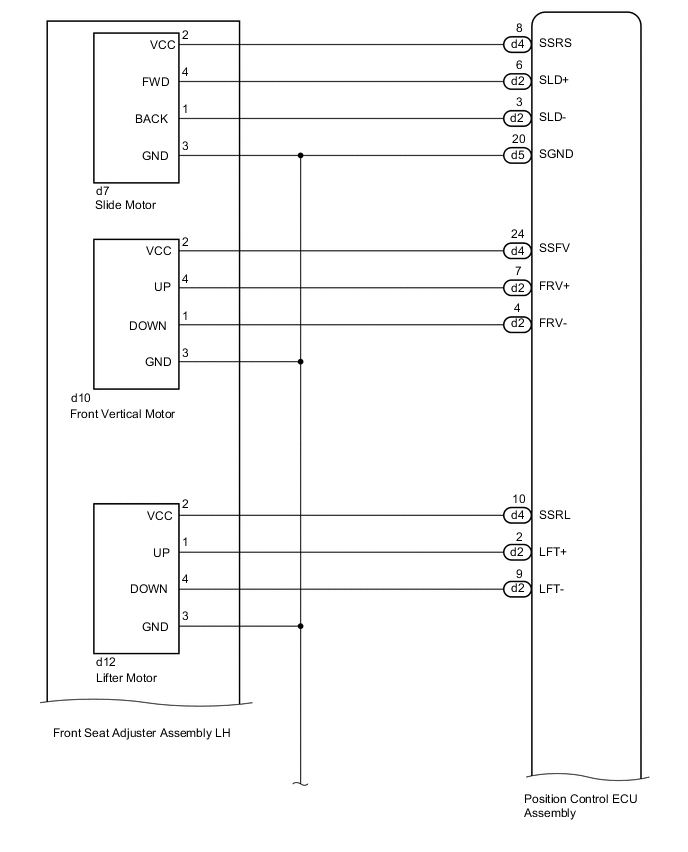
INSPECT FRONT SEAT ADJUSTER ASSEMBLY LH
Tech Tips
Check the motor operation of applicable function.
-
Text in Illustration *a Component without harness connected
(Front Seat Adjuster Assembly LH [Slide Motor])
Check the operation of the slide motor.
-
Disconnect the d7 front seat adjuster assembly LH connector.
-
Check if the slide motor moves smoothly when the battery is connected to the slide motor connector terminals.
OK Measurement Condition Operational Direction Battery positive (+) → 4 (FWD)
Battery negative (-) → 1 (BACK)
Forward Battery positive (+) → 1 (BACK)
Battery negative (-) → 4 (FWD)
Backward
-
-
Text in Illustration *a Component without harness connected
(Front Seat Adjuster Assembly LH [Front Vertical Motor])
Check the operation of the front vertical motor.
-
Disconnect the d10 front seat adjuster LH assembly connector.
-
Check if the front vertical motor moves smoothly when the battery is connected to the front vertical motor connector terminals.
OK Measurement Condition Operational Direction Battery positive (+) → 4 (UP)
Battery negative (-) → 1 (DOWN)
Upward Battery positive (+) → 1 (DOWN)
Battery negative (-) → 4 (UP)
Downward
-
-
Text in Illustration *a Component without harness connected
(Front Seat Adjuster Assembly LH [Lifter Motor])
Check the operation of the lifter motor.
-
Disconnect the d12 front seat adjuster assembly LH connector.
-
Check if the lifter motor moves smoothly when the battery is connected to the lifter motor connector terminals.
OK Measurement Condition Operational Direction Battery positive (+) → 1 (UP)
Battery negative (-) → 4 (DOWN)
Upward Battery positive (+) → 4 (DOWN)
Battery negative (-) → 1 (UP)
Downward
-
-
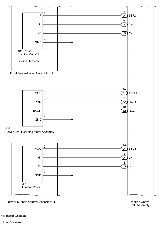
Text in Illustration *a Component without harness connected
(Front Seat Adjuster Assembly LH [Cushion Motor])
Check the operation of the cushion motor (except Ottoman).
-
Disconnect the d9 front seat adjuster assembly LH connector.
-
Check if the cushion motor moves smoothly when the battery is connected to the cushion motor connector terminals.
OK Measurement Condition Operational Direction Battery positive (+) → 1 (SI)
Battery negative (-) → 4 (SO)
Forward Battery positive (+) → 4 (SO)
Battery negative (-) → 1 (SI)
Backward
-
-
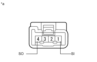
Text in Illustration *a Component without harness connected
(Front Seat Adjuster Assembly LH [Ottoman Motor])
Check the operation of the ottoman motor (for Ottoman).
-
Disconnect the d35 front seat adjuster assembly LH connector.
-
Check if the ottoman motor moves smoothly when the battery is connected to the ottoman motor connector terminals.
OK Measurement Condition Operational Direction Battery positive (+) → 1 (SI)
Battery negative (-) → 4 (SO)
Forward Battery positive (+) → 4 (SO)
Battery negative (-) → 1 (SI)
Backward
-
NG
REPLACE FRONT SEAT ADJUSTER ASSEMBLY LH Click here
OK
-
-
CHECK HARNESS AND CONNECTOR (POSITION CONTROL ECU ASSEMBLY - FRONT SEAT ADJUSTER ASSEMBLY LH)
-
*1: except Ottoman
-
*2: for Ottoman
-
Disconnect the d2, d4 and d5 position control ECU assembly connectors.
-
Disconnect the d7, d9*1, d10, d12 and d35*2 front seat adjuster assembly LH connectors.
-
Measure the resistance according to the value(s) in the table below.
Standard Resistance Tester Connection Condition Specified Condition d4-8 (SSRS) - d7-2 (VCC) Always Below 1 Ω d2-6 (SLD+) - d7-4 (FWD) Always Below 1 Ω d2-3 (SLD-) - d7-1 (BACK) Always Below 1 Ω d5-20 (SGND) - d7-3 (GND) Always Below 1 Ω d4-24 (SSFV) - d10-2 (VCC) Always Below 1 Ω d2-7 (FRV+) - d10-4 (UP) Always Below 1 Ω d2-4 (FRV-) - d10-1 (DOWN) Always Below 1 Ω d5-20 (SGND) - d10-3 (GND) Always Below 1 Ω d4-10 (SSRL) - d12-2 (VCC) Always Below 1 Ω d2-2 (LFT+) - d12-1 (UP) Always Below 1 Ω d2-9 (LFT-) - d12-4 (DOWN) Always Below 1 Ω d5-20 (SGND) - d12-3 (GND) Always Below 1 Ω d4-3 (SSRC) - d9-2 (P)*1 Always Below 1 Ω d4-6 (C+) - d9-1 (SI)*1 Always Below 1 Ω d5-4 (C-) - d9-4 (SO)*1 Always Below 1 Ω d5-20 (SGND) - d9-3 (GND)*1 Always Below 1 Ω d4-3 (SSRC) - d35-2 (P)*2 Always Below 1 Ω d4-6 (C+) - d35-1 (SI)*2 Always Below 1 Ω d5-4 (C-) - d35-4 (SO)*2 Always Below 1 Ω d5-20 (SGND) - d35-3 (GND)*2 Always Below 1 Ω d4-8 (SSRS) - Body ground Always 10 kΩ or higher d2-6 (SLD+) - Body ground Always 10 kΩ or higher d2-3 (SLD-) - Body ground Always 10 kΩ or higher d5-20 (SGND) - Body ground Always 10 kΩ or higher d4-24 (SSFV) - Body ground Always 10 kΩ or higher d2-7 (FRV+) - Body ground Always 10 kΩ or higher d2-4 (FRV-) - Body ground Always 10 kΩ or higher d4-10 (SSRL) - Body ground Always 10 kΩ or higher d2-2 (LFT+) - Body ground Always 10 kΩ or higher d2-9 (LFT-) - Body ground Always 10 kΩ or higher d4-3 (SSRC) - Body ground Always 10 kΩ or higher d4-6 (C+) - Body ground Always 10 kΩ or higher d5-4 (C-) - Body ground Always 10 kΩ or higher
OK
REPLACE POSITION CONTROL ECU ASSEMBLY Click here
NG
REPAIR OR REPLACE HARNESS OR CONNECTOR
-
-
PERFORM ACTIVE TEST USING GTS (SEAT RECLINING)
-
Connect the GTS to the DLC3.
-
Turn the power switch on (IG).
-
Turn the GTS on.
-
Enter the following menus: Body Electrical / Passenger Seat / Active Test.
-
Perform the Active Test according to the display on the GTS.
Passenger Seat Tester Display Test Part Control Range Seat Reclining Seat reclining operation Front / OFF / Rear Result Result Proceed to Reclining function operate normally A Reclining function does not operate B
B
INSPECT POWER SEAT RECLINING MOTOR ASSEMBLY Click here
A
-
-
CHECK HARNESS AND CONNECTOR (POSITION CONTROL ECU ASSEMBLY - POWER SEAT SWITCH ASSEMBLY)
-
Disconnect the d4 and d5 position control ECU assembly connectors.
-
Disconnect the d18 power seat switch assembly connector.
-
Measure the resistance according to the value(s) in the table below.
Standard Resistance Tester Connection Condition Specified Condition d5-25 (SWS1) - d18-1 (B) Always Below 1 Ω d4-20 (SWD3) - d18-10 (SPR) Always Below 1 Ω d4-11 (SWD4) - d18-11 (IG) Always Below 1 Ω d5-25 (SWS1) - Body ground Always 10 kΩ or higher d4-20 (SWD3) - Body ground Always 10 kΩ or higher d4-11 (SWD4) - Body ground Always 10 kΩ or higher
NG
REPAIR OR REPLACE HARNESS OR CONNECTOR
OK
-
-
CHECK HARNESS AND CONNECTOR (POSITION CONTROL ECU ASSEMBLY - FRONT POWER SEAT SWITCH ASSEMBLY LH)
-
Disconnect the d5 position control ECU assembly connector.
-
Disconnect the d27 front power seat switch assembly LH connector.
-
Measure the resistance according to the value(s) in the table below.
Standard Resistance Tester Connection Condition Specified Condition d5-17 (HRFS) - d27-2 (RCLF) Always Below 1 Ω d5-21 (HRRS) - d27-1 (RCLR) Always Below 1 Ω d5-20 (SGND) - d27-3 (B) Always Below 1 Ω d5-17 (HRFS) - Body ground Always 10 kΩ or higher d5-21 (HRRS) - Body ground Always 10 kΩ or higher d5-20 (SGND) - Body ground Always 10 kΩ or higher
NG
REPAIR OR REPLACE HARNESS OR CONNECTOR
OK
-
-
INSPECT FRONT POWER SEAT SWITCH ASSEMBLY LH
-
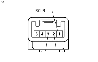
Text in Illustration *a Component without harness connected
(Front Power Seat Switch Assembly LH)
Remove the front power seat switch assembly LH Click here.
-
Measure the resistance according to the value(s) in the table below.
Standard Resistance Tester Connection Switch Condition Specified Condition 2 (RCLF) - 3 (B) Reclining switch front on Below 1 Ω 1 (RCLR) - 3 (B) Reclining switch rear on Below 1 Ω
NG
REPLACE FRONT POWER SEAT SWITCH ASSEMBLY LH Click here
OK
-
-
CHECK POWER SEAT SWITCH ASSEMBLY
-
Temporarily replace the power seat switch assembly with a new or normally functioning one Click here.
-
Check the front power seat control system Click here.
OK Power seat operates normally
OK
END (POWER SEAT SWITCH ASSEMBLY WAS DEFECTIVE)
NG
REPLACE POSITION CONTROL ECU ASSEMBLY Click here
-
-
INSPECT POWER SEAT RECLINING MOTOR ASSEMBLY
-
Text in Illustration *a Component without harness connected
(Power Seat Reclining Motor Assembly)
Check the operation of the reclining motor.
-
Disconnect the d25 power seat reclining motor assembly connector.
-
Check if the reclining motor moves smoothly when the battery is connected to the reclining motor connector terminals.
OK Measurement Condition Operational Direction Battery positive (+) → 4 (FWD)
Battery negative (-) → 1 (BACK)
Forward Battery positive (+) → 1 (BACK)
Battery negative (-) → 4 (FWD)
Backward
-
NG
REPLACE POWER SEAT RECLINING MOTOR ASSEMBLY Click here
OK
-
-
CHECK HARNESS AND CONNECTOR (POSITION CONTROL ECU ASSEMBLY - POWER SEAT MOTOR ASSEMBLY)
-
Disconnect the d2, d4 and d5 position control ECU assembly connectors.
-
Disconnect the d25 power seat reclining motor assembly connector.
-
Measure the resistance according to the value(s) in the table below.
Standard Resistance Tester Connection Condition Specified Condition d4-14 (SSRR) - d25-2 (VCC) Always Below 1 Ω d2-8 (RCL+) - d25-4 (FWD) Always Below 1 Ω d2-10 (RCL-) - d25-1 (BACK) Always Below 1 Ω d5-20 (SGND) - c25-3 (GND) Always Below 1 Ω d4-14 (SSRR) - Body ground Always 10 kΩ or higher d2-8 (RCL+) - Body ground Always 10 kΩ or higher d2-10 (RCL-) - Body ground Always 10 kΩ or higher d5-20 (SGND) - Body ground Always 10 kΩ or higher
OK
REPLACE POSITION CONTROL ECU ASSEMBLY Click here
NG
REPAIR OR REPLACE HARNESS OR CONNECTOR
-
-
PERFORM ACTIVE TEST USING GTS
-
Connect the GTS to the DLC3.
-
Turn the power switch on (IG).
-
Turn the GTS on.
-
Enter the following menus: Body Electrical / Passenger Seat / Active Test.
-
Perform the Active Test according to the display on the GTS.
Passenger Seat Tester Display Test Part Control Range Lumbar Slide Seat lumbar operation Front / OFF / Rear Pelvis Support Operation Seat pelvis operation Front / OFF / Rear Result Result Proceed to Lumbar support adjustment and pelvis functions operate normally A Lumbar support adjustment or pelvis function does not operate B
B
INSPECT LUMBAR SUPPORT ADJUSTER ASSEMBLY LH Click here
A
-
-
CHECK HARNESS AND CONNECTOR (POSITION CONTROL ECU ASSEMBLY - POWER SEAT SWITCH ASSEMBLY)
-
Disconnect the d4 and d5 position control ECU assembly connectors.
-
Disconnect the d18 power seat switch assembly connector.
-
Measure the resistance according to the value(s) in the table below.
Standard Resistance Tester Connection Condition Specified Condition d5-25 (SWS1) - d18-1 (B) Always Below 1 Ω d5-23 (SWS2) - d18-4 (E) Always Below 1 Ω d5-16 (SWS3) - d18-3 (1) Always Below 1 Ω d5-14 (SWS4) - d18-5 (2) Always Below 1 Ω d4-18 (SWD1) - d18-12 (B) Always Below 1 Ω d4-19 (SWD2) - d18-13 (CLS) Always Below 1 Ω d4-20 (SWD3) - d18-10 (SPR) Always Below 1 Ω d4-11 (SWD4) - d18-11 (IG) Always Below 1 Ω d4-21 (SWD5) - d18-14 (E) Always Below 1 Ω d5-25 (SWS1) - Body ground Always 10 kΩ or higher d5-23 (SWS2) - Body ground Always 10 kΩ or higher d5-16 (SWS3) - Body ground Always 10 kΩ or higher d5-14 (SWS4) - Body ground Always 10 kΩ or higher d4-18 (SWD1) - Body ground Always 10 kΩ or higher d4-19 (SWD2) - Body ground Always 10 kΩ or higher d4-20 (SWD3) - Body ground Always 10 kΩ or higher d4-11 (SWD4) - Body ground Always 10 kΩ or higher d4-21 (SWD5) - Body ground Always 10 kΩ or higher
NG
REPAIR OR REPLACE HARNESS OR CONNECTOR
OK
-
-
CHECK POWER SEAT SWITCH ASSEMBLY
-
Temporarily replace the power seat switch assembly with a new or normally functioning one Click here.
-
Check the front power seat control system Click here.
OK Power seat operates normally
OK
END (POWER SEAT SWITCH ASSEMBLY WAS DEFECTIVE)
NG
REPLACE POSITION CONTROL ECU ASSEMBLY Click here
-
-
INSPECT LUMBAR SUPPORT ADJUSTER ASSEMBLY LH
-
Text in Illustration *a Component without harness connected
(Lumbar Support Adjuster Assembly LH [Lumbar Motor])
Check the operation of the lumbar motor.
-
Disconnect the d31 lumbar support adjuster assembly LH connector.
-
Check if the lumbar motor moves smoothly when the battery is connected to the lumbar motor connector terminals.
OK Measurement Condition Operational Direction Battery positive (+) → 1 (H1)
Battery negative (-) → 4 (R1)
Forward Battery positive (+) → 4 (R1)
Battery negative (-) → 1 (H1)
Backward
-
-
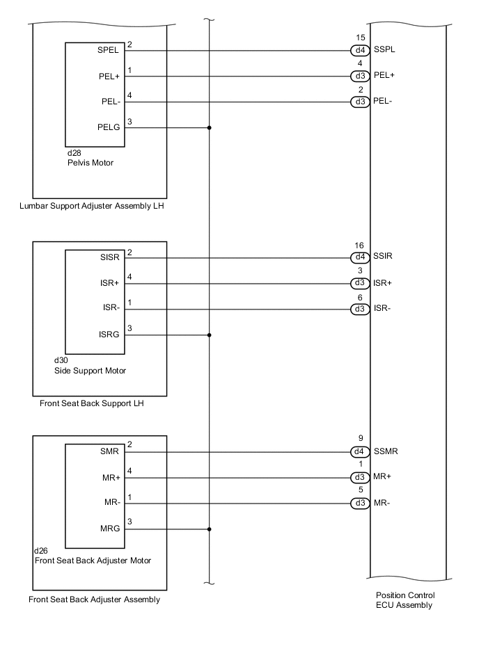
Text in Illustration *a Component without harness connected
(Lumbar Support Adjuster Assembly LH [Pelvis Motor])
Check the operation of the pelvis motor.
-
Disconnect the d28 lumbar support adjuster assembly LH connector.
-
Check if the pelvis motor moves smoothly when the battery is connected to the pelvis motor connector terminals.
OK Measurement Condition Operational Direction Battery positive (+) → 1 (PEL+)
Battery negative (-) → 4 (PEL-)
Forward Battery positive (+) → 4 (PEL-)
Battery negative (-) → 1 (PEL+)
Backward
-
NG
REPLACE LUMBAR SUPPORT ADJUSTER ASSEMBLY LH Click here
OK
-
-
CHECK HARNESS AND CONNECTOR (POSITION CONTROL ECU ASSEMBLY - LUMBAR SUPPORT ADJUSTER ASSEMBLY LH)
-
Disconnect the d3, d4 and d5 position control ECU assembly connectors.
-
Disconnect the d28 and d31 lumbar support adjuster assembly LH connectors.
-
Measure the resistance according to the value(s) in the table below.
Standard Resistance Tester Connection Condition Specified Condition d4-13 (SSLB) - d31-2 (VCC) Always Below 1 Ω d4-5 (L+) - d31-1 (H1) Always Below 1 Ω d5-3 (L-) - d31-4 (R1) Always Below 1 Ω d5-20 (SGND) - d31-3 (GND) Always Below 1 Ω d4-15 (SSPL) - d28-2 (SPEL) Always Below 1 Ω d3-4 (PEL+) - d28-1 (PEL+) Always Below 1 Ω d3-2 (PEL-) - d28-4 (PEL-) Always Below 1 Ω d5-20 (SGND) - d28-3 (PELG) Always Below 1 Ω d4-13 (SSLB) - Body ground Always 10 kΩ or higher d4-5 (L+) - Body ground Always 10 kΩ or higher d5-3 (L-) - Body ground Always 10 kΩ or higher d5-20 (SGND) - Body ground Always 10 kΩ or higher d4-15 (SSPL) - Body ground Always 10 kΩ or higher d3-4 (PEL+) - Body ground Always 10 kΩ or higher d3-2 (PEL-) - Body ground Always 10 kΩ or higher
OK
REPLACE POSITION CONTROL ECU ASSEMBLY Click here
NG
REPAIR OR REPLACE HARNESS OR CONNECTOR
-
-
PERFORM ACTIVE TEST USING GTS
-
Connect the GTS to the DLC3.
-
Turn the power switch on (IG).
-
Turn the GTS on.
-
Enter the following menus: Body Electrical / Passenger Seat / Active Test.
-
Perform the Active Test according to the display on the GTS.
Passenger Seat Tester Display Test Part Control Range Side Support Operation Seat side support operation Open / OFF / Close Rear Seat Lumbar Adjustment Seat back adjustment operation Front / OFF / Rear Result Result Proceed to Side support and front seat back adjuster functions operate normally A Side support function does not operate B Front seat back adjuster function does not operate C
B
INSPECT FRONT SEAT BACK SUPPORT LH Click here
C
INSPECT FRONT SEAT BACK ADJUSTER ASSEMBLY Click here
A
-
-
CHECK HARNESS AND CONNECTOR (POSITION CONTROL ECU ASSEMBLY - POWER SEAT SWITCH ASSEMBLY)
-
Disconnect the d4 and d5 position control ECU assembly connectors.
-
Disconnect the d18 power seat switch assembly connector.
-
Measure the resistance according to the value(s) in the table below.
Standard Resistance Tester Connection Condition Specified Condition d5-25 (SWS1) - d18-1 (B) Always Below 1 Ω d5-23 (SWS2) - d18-4 (E) Always Below 1 Ω d5-16 (SWS3) - d18-3 (1) Always Below 1 Ω d5-14 (SWS4) - d18-5 (2) Always Below 1 Ω d4-18 (SWD1) - d18-12 (B) Always Below 1 Ω d4-19 (SWD2) - d18-13 (CLS) Always Below 1 Ω d4-20 (SWD3) - d18-10 (SPR) Always Below 1 Ω d4-11 (SWD4) - d18-11 (IG) Always Below 1 Ω d4-21 (SWD5) - d18-14 (E) Always Below 1 Ω d5-25 (SWS1) - Body ground Always 10 kΩ or higher d5-23 (SWS2) - Body ground Always 10 kΩ or higher d5-16 (SWS3) - Body ground Always 10 kΩ or higher d5-14 (SWS4) - Body ground Always 10 kΩ or higher d4-18 (SWD1) - Body ground Always 10 kΩ or higher d4-19 (SWD2) - Body ground Always 10 kΩ or higher d4-20 (SWD3) - Body ground Always 10 kΩ or higher d4-11 (SWD4) - Body ground Always 10 kΩ or higher d4-21 (SWD5) - Body ground Always 10 kΩ or higher
NG
REPAIR OR REPLACE HARNESS OR CONNECTOR
OK
-
-
CHECK POWER SEAT SWITCH ASSEMBLY
-
Temporarily replace the power seat switch assembly with a new or normally functioning one Click here.
-
Check the front power seat control system Click here.
OK Power seat operates normally
OK
END (POWER SEAT SWITCH ASSEMBLY WAS DEFECTIVE)
NG
REPLACE POSITION CONTROL ECU ASSEMBLY Click here
-
-
INSPECT FRONT SEAT BACK SUPPORT LH
-
Text in Illustration *a Component without harness connected
(Front Seat Back Support LH [Side Support Motor])
Check the operation of the side support motor.
-
Disconnect the d30 front seat back support LH connector.
-
Check if the side support motor moves smoothly when the battery is connected to the side support motor connector terminals.
OK Measurement Condition Operational Direction Battery positive (+) → 4 (ISR+)
Battery negative (-) → 1 (ISR-)
Paddle Open Battery positive (+) → 1 (ISR-)
Battery negative (-) → 4 (ISR+)
Paddle Close
-
NG
REPLACE FRONT SEAT BACK SUPPORT LH Click here
OK
-
-
CHECK HARNESS AND CONNECTOR (POSITION CONTROL ECU ASSEMBLY - FRONT SEAT BACK SUPPORT LH)
-
Disconnect the d3, d4 and d5 position control ECU assembly connectors.
-
Disconnect the d30 front seat back support LH connector.
-
Measure the resistance according to the value(s) in the table below.
Standard Resistance Tester Connection Condition Specified Condition d4-16 (SSIR) - d30-2 (SISR) Always Below 1 Ω d3-3 (ISR+) - d30-4 (ISR+) Always Below 1 Ω d3-6 (ISR-) - d30-1 (ISR-) Always Below 1 Ω d5-20 (SGND) - d30-3 (ISRG) Always Below 1 Ω d4-16 (SSIR) - Body ground Always 10 kΩ or higher d3-3 (ISR+) - Body ground Always 10 kΩ or higher d3-6 (ISR-) - Body ground Always 10 kΩ or higher d5-20 (SGND) - Body ground Always 10 kΩ or higher
OK
REPLACE POSITION CONTROL ECU ASSEMBLY Click here
NG
REPAIR OR REPLACE HARNESS OR CONNECTOR
-
-
INSPECT FRONT SEAT BACK ADJUSTER ASSEMBLY
-
Text in Illustration *a Component without harness connected
(Front Seat Back Adjuster Assembly [Front Seat Back Adjuster Motor])
Check the operation of the front seat back adjuster motor.
-
Disconnect the d26 front seat back adjuster assembly connector.
-
Check if the front seat back adjuster motor moves smoothly when the battery is connected to the front seat back adjuster motor connector terminals.
OK Measurement Condition Operational Direction Battery positive (+) → 4 (MR+)
Battery negative (-) → 1 (MR-)
Forward Battery positive (+) → 1 (MR-)
Battery negative (-) → 4 (MR+)
Backward
-
NG
REPLACE FRONT SEAT BACK ADJUSTER ASSEMBLY Click here
OK
-
-
CHECK HARNESS AND CONNECTOR (POSITION CONTROL ECU ASSEMBLY - FRONT SEAT BACK ADJUSTER ASSEMBLY)
-
Disconnect the d3, d4 and d5 position control ECU assembly connectors.
-
Disconnect the d26 front seat back adjuster assembly connector.
-
Measure the resistance according to the value(s) in the table below.
Standard Resistance Tester Connection Condition Specified Condition d4-9 (SSMR) - d26-2 (SMR) Always Below 1 Ω d3-1 (MR+) - d26-4 (MR+) Always Below 1 Ω d3-5 (MR-) - d26-1 (MR-) Always Below 1 Ω d5-20 (SGND) - d26-3 (MRG) Always Below 1 Ω d4-9 (SSMR) - Body ground Always 10 kΩ or higher d3-1 (MR+) - Body ground Always 10 kΩ or higher d3-5 (MR-) - Body ground Always 10 kΩ or higher d5-20 (SGND) - Body ground Always 10 kΩ or higher
OK
REPLACE POSITION CONTROL ECU ASSEMBLY Click here
NG
REPAIR OR REPLACE HARNESS OR CONNECTOR
-