METER / GAUGE SYSTEM, Diagnostic DTC:B1507, B1508
| DTC Code | DTC Name |
|---|---|
| B1507 | Open in Turn Signal Circuit |
| B1508 | Short in Turn Signal / Hazard Flasher Circuit |
DESCRIPTION
These DTCs are stored when the combination meter assembly detects an open in a turn signal light circuit, a short in a turn signal light circuit, or a short in the hazard warning light circuit.
| DTC Code | DTC Detection Condition | Trouble Area |
|---|---|---|
| B1507 | When IG voltage is 9.5 V or more and the following condition is detected:
|
|
| B1508 | When IG voltage is 9.5 V or more and the following condition is detected:
|
-
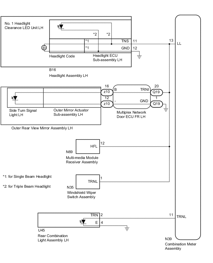
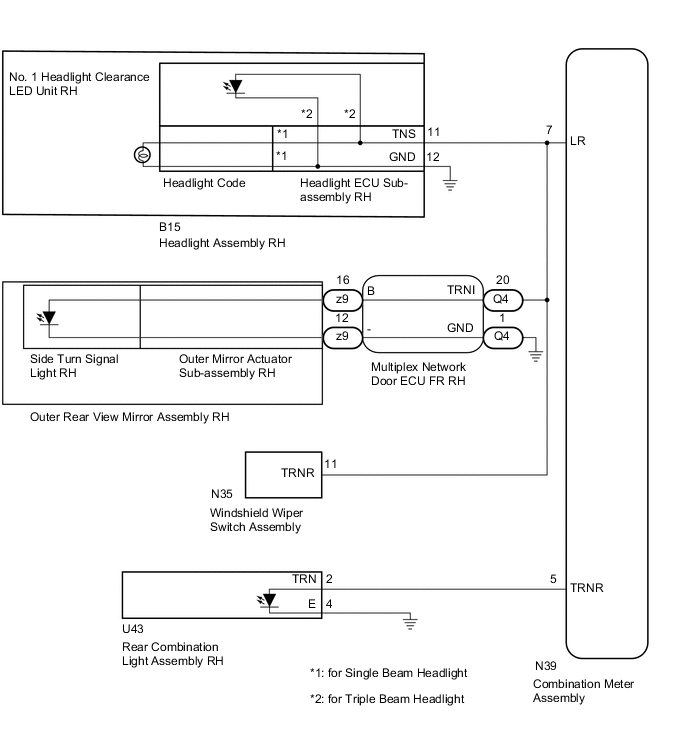
*1: for Single Beam Headlight
-
*2: for Triple Beam Headlight
WIRING DIAGRAM
CAUTION / NOTICE / HINT
Note
Inspect the bulbs for circuits related to this system before performing the following inspection procedure.
PROCEDURE
-
CLEAR DTC
NEXT 
-
CHECK FOR DTC
-
Clear the DTCs Click here.
-
Check for DTCs Click here.
OK DTC B1507 or B1508 output does not occur.
OK 
USE SIMULATION METHOD TO CHECK Click here
NG
-
-
CONFIRM MALFUNCTIONING LIGHT
-
Check the malfunctioning turn signal light.
Result Result Proceed to LH side front or side turn signal light does not illuminate. A RH side front or side turn signal light does not illuminate. B LH side rear turn signal light does not illuminate. C RH side rear turn signal light does not illuminate. D
B 
CHECK HARNESS AND CONNECTOR (RH SIDE TURN SIGNAL CIRCUIT) Click here
C
CHECK HARNESS AND CONNECTOR (LH SIDE TURN SIGNAL CIRCUIT) Click here
D
CHECK HARNESS AND CONNECTOR (RH SIDE TURN SIGNAL CIRCUIT) Click here
A
-
-
CHECK HARNESS AND CONNECTOR (LH SIDE TURN SIGNAL CIRCUIT)
-
Disconnect the N39 combination meter assembly connector.
-
Disconnect the z10 front multiplex network door ECU LH connector.
-
Disconnect the B16 headlight assembly LH connector.
-
Disconnect the N69 multi-media module receiver assembly connector.
-
Disconnect the N35 windshield wiper switch assembly connector.
-
Measure the resistance according to the value(s) in the table below.
Standard Resistance Tester Connection Condition Specified Condition N39-13 (LL) - B16-11 (TNS) Always Below 1 Ω N39-13 (LL) - z10-16 (B) N39-13 (LL) - N69-12 (HFL) N39-13 (LL) - N35-1 (TRNL) B16-12 (GND) - Body ground z10-12 (-) - Body ground N39-13 (LL) - Body ground Always 10 kΩ or higher
NG
CHECK FRONT MULTIPLEX NETWORK DOOR ECU LH Click here
OK
-
-
INSPECT OUTER REAR VIEW MIRROR ASSEMBLY LH
-
Remove the outer rear view mirror assembly LH Click here.
-
Inspect the outer rear view mirror assembly LH Click here.
OK Light comes on.
NG
INSPECT SIDE TURN SIGNAL LIGHT ASSEMBLY LH Click here
OK
-
-
CHECK HEADLIGHT ECU SUB-ASSEMBLY LH
-
Remove the headlight ECU sub-assembly LH Click here.
-
Measure the resistance according to the value(s) in the table below.
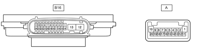
Standard Resistance Tester Connection Condition Specified Condition B16-11 (TNS) - A-9 (TURN+) Always Below 1 Ω B16-12 (GND) - A-13 (TURN-) B16-11 (TNS) - B16-12 (GND) Always 10 kΩ or higher Result Result Proceed to OK (for Single Beam Headlight) A OK (for Triple Beam Headlight) B NG C
B
CHECK NO. 1 HEADLIGHT CLEARANCE LED UNIT LH Click here
C
REPLACE HEADLIGHT ECU SUB-ASSEMBLY LH Click here
A
-
-
CHECK HEADLIGHT CORD
-
Replace the headlight code Click here.
-
Clear the DTCs Click here.
-
Check for DTCs Click here.
OK DTC B1507 or B1508 output does not occur.
OK
END (HEADLIGHT CODE IS DEFECTIVE)
NG
REPLACE COMBINATION METER ASSEMBLY Click here
-
-
CHECK FRONT MULTIPLEX NETWORK DOOR ECU LH
-
Disconnect the Q19 and z10 front multiplex network door ECU LH.
-
Measure the resistance according to the value(s) in the table below.
Standard Resistance Tester Connection Condition Specified Condition Q19-20 (TRNI) - z10-16 (B) Always Below 1 Ω Q19-1 (GND) - z10-12 (-) Q19-20 (TRNI) - Q19-1 (GND) Always 10 kΩ or higher Q19-20 (TRNI) - Body ground
OK
REPAIR OR REPLACE HARNESS OR CONNECTOR
NG
REPLACE FRONT MULTIPLEX NETWORK DOOR ECU LH Click here
-
-
INSPECT SIDE TURN SIGNAL LIGHT ASSEMBLY LH
-
Remove the side turn signal light assembly LH Click here.
-
Inspect the side turn signal light assembly LH Click here.
OK
REPLACE OUTER MIRROR ACTUATOR ASSEMBLY LH
NG
REPLACE SIDE TURN SIGNAL LIGHT ASSEMBLY LH Click here
-
-
CHECK NO. 1 HEADLIGHT CLEARANCE LED UNIT LH
-
Replace the No. 1 headlight clearance LED unit LH Click here.
-
Clear the DTCs Click here.
-
Check for DTCs Click here.
OK DTC B1507 or B1508 output does not occur.
OK
END (NO. 1 HEADLIGHT CLEARANCE LED UNIT LH IS DEFECTIVE)
NG
REPLACE COMBINATION METER ASSEMBLY Click here
-
-
CHECK HARNESS AND CONNECTOR (RH SIDE TURN SIGNAL CIRCUIT)
-
Disconnect the N39 combination meter assembly connector.
-
Disconnect the B15 headlight assembly RH connector.
-
Disconnect the z9 front multiplex network door ECU RH connector.
-
Disconnect the N35 windshield wiper switch assembly connector.
-
Measure the resistance according to the value(s) in the table below.
Standard Resistance Tester Connection Condition Specified Condition N39-7 (LR) - B15-11 (TNS) Always Below 1 Ω N39-7 (LR) - z9-16 (B) N39-7 (LR) - N35-11 (TRNR) B15-12 (GND) - Body ground z9-12 (-) - Body ground N39-7 (LR) - Body ground Always 10 kΩ or higher
NG
CHECK FRONT MULTIPLEX NETWORK DOOR ECU RH Click here
OK
-
-
INSPECT OUTER REAR VIEW MIRROR ASSEMBLY RH
-
Remove the outer rear view mirror assembly RH Click here.
-
Inspect the outer rear view mirror assembly RH Click here.
NG
INSPECT SIDE TURN SIGNAL LIGHT ASSEMBLY RH Click here
OK
-
-
CHECK HEADLIGHT ECU SUB-ASSEMBLY RH
-
Remove the headlight ECU sub-assembly RH Click here.
-
Measure the resistance according to the value(s) in the table below.
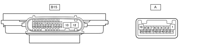
Standard Resistance Tester Connection Condition Specified Condition B15-11 (TNS) - A-9 (TURN+) Always Below 1 Ω B15-12 (GND) - A-13 (TURN-) B15-11 (TNS) - B15-12 (GND) Always 10 kΩ or higher Result Result Proceed to OK (for Single Beam Headlight) A OK (for Triple Beam Headlight) B NG C
B
CHECK NO. 1 HEADLIGHT CLEARANCE LED UNIT RH Click here
C
REPLACE HEADLIGHT ECU SUB-ASSEMBLY RH Click here
A
-
-
CHECK HEADLIGHT CORD
-
Replace the headlight code Click here.
-
Clear the DTCs Click here.
-
Check for DTCs Click here.
OK DTC B1507 or B1508 output does not occur.
OK
END (HEADLIGHT CODE IS DEFECTIVE)
NG
REPLACE COMBINATION METER ASSEMBLY Click here
-
-
CHECK FRONT MULTIPLEX NETWORK DOOR ECU RH
-
Disconnect the Q4 and z9 front multiplex network door ECU RH.
-
Measure the resistance according to the value(s) in the table below.
Standard Resistance Tester Connection Condition Specified Condition Q4-20 (TRNI) - z9-16 (B) Always Below 1 Ω Q4-1 (GND) - z9-12 (-) Q4-20 (TRNI) - Q4-1 (GND) Always 10 kΩ or higher Q4-20 (TRNI) - Body ground
OK
REPAIR OR REPLACE HARNESS OR CONNECTOR
NG
REPLACE FRONT MULTIPLEX NETWORK DOOR ECU RH Click here
-
-
INSPECT SIDE TURN SIGNAL LIGHT ASSEMBLY RH
-
Remove the side turn signal light assembly RH Click here.
-
Inspect the side turn signal light assembly RH Click here.
OK
REPLACE OUTER MIRROR ACTUATOR ASSEMBLY RH
NG
REPLACE SIDE TURN SIGNAL LIGHT ASSEMBLY RH Click here
-
-
CHECK NO. 1 HEADLIGHT CLEARANCE LED UNIT RH
-
Replace the No. 1 headlight clearance LED unit RH Click here.
-
Clear the DTCs Click here.
-
Check for DTCs Click here.
OK DTC B1507 or B1508 output does not occur.
OK
END (NO. 1 HEADLIGHT CLEARANCE LED UNIT RH IS DEFECTIVE)
NG
REPLACE COMBINATION METER ASSEMBLY Click here
-
-
CHECK HARNESS AND CONNECTOR (LH SIDE TURN SIGNAL CIRCUIT)
-
Disconnect the N39 combination meter assembly connector.
-
Disconnect the U45 rear combination light assembly LH connector.
-
Measure the resistance according to the value(s) in the table below.
Standard Resistance Tester Connection Condition Specified Condition N39-11 (TRNL) - U45-2 (TRN) Always Below 1 Ω U45-4 (E) - Body ground N39-11 (TRNL) - Body ground Always 10 kΩ or higher
NG
REPAIR OR REPLACE HARNESS OR CONNECTOR
OK
-
-
CHECK REAR COMBINATION LIGHT ASSEMBLY LH
-
Remove the rear combination light assembly LH Click here.
-
Inspect the rear combination light assembly LH Click here.
OK
REPLACE COMBINATION METER ASSEMBLY Click here
NG
REPLACE REAR COMBINATION LIGHT ASSEMBLY LH Click here
-
-
CHECK HARNESS AND CONNECTOR (RH SIDE TURN SIGNAL CIRCUIT)
-
Disconnect the N39 combination meter assembly connector.
-
Disconnect the U43 rear combination light assembly RH connector.
-
Measure the resistance according to the value(s) in the table below.
Standard Resistance Tester Connection Condition Specified Condition N39-5 (TRNR) - U43-2 (TRN) Always Below 1 Ω U43-4 (E) - Body ground N39-5 (TRNR) - Body ground Always 10 kΩ or higher
NG
REPAIR OR REPLACE HARNESS OR CONNECTOR
OK
-
-
CHECK REAR COMBINATION LIGHT ASSEMBLY RH
-
Remove the rear combination light assembly RH Click here.
-
Inspect the rear combination light assembly RH Click here.
OK
REPLACE COMBINATION METER ASSEMBLY Click here
NG
REPLACE REAR COMBINATION LIGHT ASSEMBLY RH Click here
-