METER / GAUGE SYSTEM, Diagnostic DTC:B150B
| DTC Code | DTC Name |
|---|---|
| B150B | Lost Communication with Gigabit Video Interface |
DESCRIPTION
The combination meter assembly receives an image information signal from the multi-media module receiver assembly through a video signal (digital) line.
Based on this signal, audio and visual system or navigation system information is displayed on the multi-information display.
This DTC is stored when the combination meter assembly cannot receive the signal.
| DTC Code | DTC Detection Condition | Trouble Area |
|---|---|---|
| B150B | After the combination meter assembly receives a registration information signal, which is sent by the radio receiver assembly when the power switch is on (ACC), 1 or more times, and reception of the "Image ON" signal is confirmed, a GVIF video signal cannot be received for 1 second or more |
|
WIRING DIAGRAM
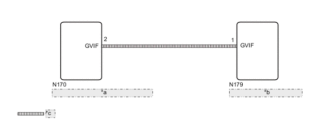
| *a | Multi-media Module Receiver Assembly |
| *b | Combination Meter Assembly |
| *c | Video signal (Digital) |
CAUTION / NOTICE / HINT
*: w/ Navigation System
Note
-
When replacing the combination meter assembly, make sure to replace it with a new one.
-
If DTCs B150B and B150A are output simultaneously, troubleshoot for B150A first Click here.
-
Depending on the parts that are replaced during vehicle inspection or maintenance, performing initialization, registration or calibration may be needed. Refer to Precaution for navigation system* or audio and visual system.
Navigation System: Click here
Audio and Visual System: Click here
PROCEDURE
-
CONFIRM MODEL
-
Choose the model to be inspected.
Result Result Proceed to w/ Navigation System A w/o Navigation System B
B 
CHECK DTC (AUDIO AND VISUAL SYSTEM) Click here
A 
-
-
CHECK DTC (NAVIGATION SYSTEM)
-
Check for DTCs Click here.
OK DTCs are not output.
NG 
GO TO NAVIGATION SYSTEM Click here
OK
-
-
CHECK DTC (AUDIO AND VISUAL SYSTEM)
-
Check for DTCs Click here.
OK DTCs are not output.
NG
GO TO AUDIO AND VISUAL SYSTEM Click here
OK
-
-
CHECK HARNESS AND CONNECTOR (GVIF CABLE)
-
Replace the harness and connector (GVIF cable) with a new or normally functioning one.
-
Turn the power switch on (IG) and wait 30 seconds.
Tech Tips
A maximum of 30 seconds is required to send/receive the registration information between the combination meter assembly and multi-media module receiver assembly.
-
Operate the steering pad switch assembly and check that the audio tab illuminates.
-
Check for DTCs and check the display status of the multi-information display Click here.
OK The audio information illuminates and DTC B150B is not output. Result Result Proceed to NG A OK B
B
END (GVIF CABLE IS DEFECTIVE)
A
-
-
CHECK COMBINATION METER ASSEMBLY
-
Replace the combination meter assembly Click here.
-
Turn the power switch on (IG) and wait 30 seconds.
Tech Tips
A maximum of 30 seconds is required to send/receive the registration information between the combination meter assembly and multi-media module receiver assembly.
-
Operate the steering pad switch assembly and check that the audio tab illuminates.
-
Check for DTCs and check the display status of the multi-information display Click here.
OK The audio information illuminates and DTC B150B is not output.
OK
END (COMBINATION METER ASSEMBLY IS DEFECTIVE)
NG
REPLACE MULTI-MEDIA MODULE RECEIVER ASSEMBLY Click here
-