LIGHTING SYSTEM Door Courtesy Switch Circuit
DESCRIPTION
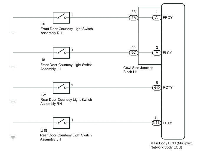
The main body ECU receives a door open or closed signal from each door courtesy light switch.
WIRING DIAGRAM
CAUTION / NOTICE / HINT
Note
-
Recognition code registration is necessary when replacing the main body ECU (multiplex network body ECU).
-
If the main body ECU (multiplex network body ECU) is replaced, refer to the Service Bulletin.
PROCEDURE
-
READ VALUE USING GTS (DOOR COURTESY LIGHT SWITCH)
-
Using the GTS, read the Data List Click here.
Main Body Tester Display Measurement Item/Range Normal Condition Diagnostic Note RR Door Courtesy SW Rear door courtesy light switch RH signal / ON or OFF ON: Rear door RH open
OFF: Rear door RH closed
- RL Door Courtesy SW Rear door courtesy light switch LH signal / ON or OFF ON: Rear door LH open
OFF: Rear door LH closed
- FR Door Courtesy Front door courtesy light switch RH signal / ON or OFF ON: Front door RH closed
OFF: Front door RH open
- FL Door Courtesy Front door courtesy light switch LH signal / ON or OFF ON: Front door LH closed
OFF: Front door LH open
- OK Normal conditions listed above are displayed. Result Result Proceed to OK A NG (Front door courtesy light switch RH does not operate) B NG (Front door courtesy light switch LH does not operate) C NG (Rear door courtesy light switch RH does not operate) D NG (Rear door courtesy light switch LH does not operate) E
A 
PROCEED TO NEXT SUSPECTED AREA SHOWN IN PROBLEM SYMPTOMS TABLE Click here
C 
INSPECT FRONT DOOR COURTESY LIGHT SWITCH LH Click here
D
INSPECT REAR DOOR COURTESY LIGHT SWITCH RH Click here
E
INSPECT REAR DOOR COURTESY LIGHT SWITCH LH Click here
B 
-
-
INSPECT FRONT DOOR COURTESY LIGHT SWITCH RH
-
Remove the front door courtesy light switch RH Click here.
-
Inspect the front door courtesy light switch RH Click here.
NG
REPLACE FRONT DOOR COURTESY LIGHT SWITCH RH Click here
OK
-
-
CHECK HARNESS AND CONNECTOR (FRONT DOOR COURTESY LIGHT SWITCH RH - COWL SIDE JUNCTION BLOCK LH)
-
Disconnect the T6 front door courtesy light switch RH connector.
-
Disconnect the 5A cowl side junction block LH connector.
-
Measure the resistance according to the value(s) in the table below.
Standard Resistance Tester Connection Condition Specified Condition T6-1 - 5A-33 Always Below 1 Ω T6-1 - Body ground Always 10 kΩ or higher
NG
REPAIR OR REPLACE HARNESS OR CONNECTOR
OK
-
-
INSPECT COWL SIDE JUNCTION BLOCK LH
-
Remove the cowl side junction block LH Click here.
-
Remove the main body ECU from the cowl side junction block LH Click here.
-
Measure the resistance according to the value(s) in the table below.
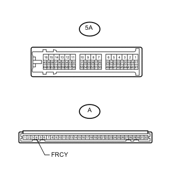
Standard Resistance Tester Connection Condition Specified Condition A-4 (FRCY) - 5A-33 Always Below 1 Ω
OK
REPLACE MAIN BODY ECU (MULTIPLEX NETWORK BODY ECU) Click here
NG
REPLACE COWL SIDE JUNCTION BLOCK LH Click here
-
-
INSPECT FRONT DOOR COURTESY LIGHT SWITCH LH
-
Remove the front door courtesy light switch LH Click here.
-
Inspect the front door courtesy light switch LH Click here.
NG
REPLACE FRONT DOOR COURTESY LIGHT SWITCH LH Click here
OK
-
-
CHECK HARNESS AND CONNECTOR (FRONT DOOR COURTESY LIGHT SWITCH LH - COWL SIDE JUNCTION BLOCK LH)
-
Disconnect the U8 front door courtesy light switch LH connector.
-
Disconnect the 5C cowl side junction block LH connector.
-
Measure the resistance according to the value(s) in the table below.
Standard Resistance Tester Connection Condition Specified Condition U8-1 - 5C-44 Always Below 1 Ω U8-1 - Body ground Always 10 kΩ or higher
NG
REPAIR OR REPLACE HARNESS OR CONNECTOR
OK
-
-
INSPECT COWL SIDE JUNCTION BLOCK LH
-
Remove the cowl side junction block LH Click here.
-
Remove the main body ECU from the cowl side junction block LH Click here.
-
Measure the resistance according to the value(s) in the table below.
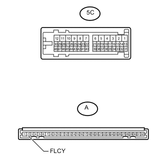
Standard Resistance Tester Connection Condition Specified Condition A-2 (FLCY) - 5C-44 Always Below 1 Ω
OK
REPLACE MAIN BODY ECU (MULTIPLEX NETWORK BODY ECU) Click here
NG
REPLACE COWL SIDE JUNCTION BLOCK LH Click here
-
-
INSPECT REAR DOOR COURTESY LIGHT SWITCH RH
-
Remove the rear door courtesy light switch RH Click here.
-
Inspect the rear door courtesy light switch RH Click here.
NG
REPLACE REAR DOOR COURTESY LIGHT SWITCH RH Click here
OK
-
-
CHECK HARNESS AND CONNECTOR (REAR DOOR COURTESY LIGHT SWITCH RH - MAIN BODY ECU)
-
Disconnect the T21 rear door courtesy light switch RH connector.
-
Disconnect the N12 main body ECU connector.
-
Measure the resistance according to the value(s) in the table below.
Standard Resistance Tester Connection Condition Specified Condition T21-1 - N12-6 (RCTY) Always Below 1 Ω T21-1 - Body ground Always 10 kΩ or higher
OK
REPLACE MAIN BODY ECU (MULTIPLEX NETWORK BODY ECU) Click here
NG
REPAIR OR REPLACE HARNESS OR CONNECTOR
-
-
INSPECT REAR DOOR COURTESY LIGHT SWITCH LH
-
Remove the rear door courtesy light switch LH Click here.
-
Inspect the rear door courtesy light switch LH Click here.
NG
REPLACE REAR DOOR COURTESY LIGHT SWITCH LH Click here
OK
-
-
CHECK HARNESS AND CONNECTOR (REAR DOOR COURTESY LIGHT SWITCH LH - MAIN BODY ECU)
-
Disconnect the U18 rear door courtesy light switch LH connector.
-
Disconnect the N11 main body ECU connector.
-
Measure the resistance according to the value(s) in the table below.
Standard Resistance Tester Connection Condition Specified Condition U18-1 - N11-3 (LCTY) Always Below 1 Ω U18-1 - Body ground Always 10 kΩ or higher
OK
REPLACE MAIN BODY ECU (MULTIPLEX NETWORK BODY ECU) Click here
NG
REPAIR OR REPLACE HARNESS OR CONNECTOR
-