WIRELESS DOOR LOCK CONTROL SYSTEM No Answer-Back
DESCRIPTION
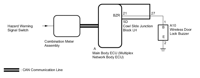
In some cases, wireless door lock control functions are normal but the hazard warning light and/or wireless door lock buzzer answer-back function(s) does not operate. In such cases, hazard warning light and wireless door lock buzzer signal outputs from the main body ECU (multiplex network body ECU) may be malfunctioning.
WIRING DIAGRAM
CAUTION / NOTICE / HINT
Note
-
The wireless door lock control system uses the CAN communication system. First, confirm that there is no malfunction in the CAN communication system. Refer to the How to Proceed with Troubleshooting procedure Click here.
Click here
-
Before performing the inspection, check that DTC B1242 (wireless door lock control) is not output Click here.
-
If the main body ECU (multiplex network body ECU) is replaced, refer to Service Bulletin.
-
When using the GTS with the power switch off to troubleshoot:
Connect the GTS to the DLC3 and turn a courtesy light switch on and off at 1.5-seconds intervals until communication between the GTS and vehicle begins.
PROCEDURE
-
CUSTOMIZE SETTING
-
Check the customize status of answer-back function has been default setting Click here.
Result Result Proceed to The customize status of answer-back function has been default setting. A The customize status of answer-back function has not been default setting. B
B 
PERFORM CUSTOMIZE FUNCTION Click here
A 
-
-
CHECK WIRELESS DOOR LOCK CONTROL FUNCTIONS
-
Check the wireless door lock control functions using the electrical key transmitter sub-assembly Click here.
OK Wireless door lock control functions are operated normally.
NG
Go to PROBLEM SYMPTOMS TABLE Click here
OK
-
-
READ VALUE USING GTS (DOOR LOCK POSITION SWITCH)
-
Use the Data List to check if the door lock positions are functioning properly Click here.
Main Body Tester Display Measurement Item/Range Normal Condition Diagnostic Note FR Door Lock Pos Front door RH unlock detection switch signal / LOCK or UNLOCK LOCK: Front door RH locked
UNLOCK: Front door RH unlocked
- FL Door Lock Pos Front door LH unlock detection switch signal / LOCK or UNLOCK LOCK: Front door LH locked
UNLOCK: Front door LH unlocked
- RR-Door Lock Pos SW Rear door RH unlock detection switch signal / ON or OFF ON: Rear door RH unlocked
OFF: Rear door RH locked
- RL-Door Lock Pos SW Rear door LH unlock detection switch signal / ON or OFF ON: Rear door LH unlocked
OFF: Rear door LH locked
- OK On tester screen, each item changes between LOCK and UNLOCK (ON and OFF) according to above chart.
NG
Go to LIGHTING SYSTEM (Proceed to Door Unlock Detection Switch Circuit) Click here
OK
-
-
CHECK WIRELESS ANSWER-BACK OPERATION
-
Check the wireless answer-back operation using the electrical key transmitter sub-assembly.
Result Result Proceed to Only wireless door lock buzzer answer-back does not occur. A Only hazard warning light answer-back does not occur. B
B 
CHECK HAZARD WARNING LIGHTS OPERATION Click here
A
-
-
PERFORM ACTIVE TEST USING GTS (WIRELESS DOOR LOCK BUZZER)
-
Operate the GTS according to the steps on the display and select Active Test Click here.
Main Body Tester Display Test Part Control Range Diagnostic Note Wireless Buzzer Wireless door lock buzzer OFF/ON - OK The wireless door lock buzzer can be turned on and off using the GTS.
OK
REPLACE MAIN BODY ECU (MULTIPLEX NETWORK BODY ECU) Click here
NG
-
-
CHECK HARNESS AND CONNECTOR (WIRELESS DOOR LOCK BUZZER - MAIN BODY ECU [MULTIPLEX NETWORK BODY ECU] AND BODY GROUND)
-
Disconnect the A10 wireless door lock buzzer connector.
-
Remove the main body ECU (multiplex network body ECU) from the cowl side junction block LH Click here.
-
Measure the resistance according to the value(s) in the table below.
Standard Resistance Tester Connection Condition Specified Condition A10-1 (B) - A-21 (BZR) Always Below 1 Ω A10-1 (B) or A-21 (BZR) - Body ground Always 10 kΩ or higher
NG
CHECK HARNESS AND CONNECTOR (WIRELESS DOOR LOCK BUZZER - COWL SIDE JUNCTION BLOCK LH) Click here
OK
-
-
CHECK HARNESS AND CONNECTOR (WIRELESS DOOR LOCK BUZZER - BODY GROUND)
-
Disconnect the A10 wireless door lock buzzer connector.
-
Measure the resistance according to the value(s) in the table below.
Standard Resistance Tester Connection Condition Specified Condition A10-2 (E) - Body ground Always Below 1 Ω
NG
REPAIR OR REPLACE HARNESS OR CONNECTOR
OK
-
-
REPLACE WIRELESS DOOR LOCK BUZZER
-
Temporarily replace the wireless door lock buzzer with a new or normally functioning one Click here.
NEXT
-
-
CHECK WIRELESS DOOR LOCK BUZZER OPERATION
-
Check the operation of the wireless answer-back function.
OK Wireless answer-back function operates normally.
OK
END (WIRELESS DOOR LOCK BUZZER IS DEFECTIVE)
NG
REPLACE MAIN BODY ECU (MULTIPLEX NETWORK BODY ECU) Click here
-
-
CHECK HARNESS AND CONNECTOR (WIRELESS DOOR LOCK BUZZER - COWL SIDE JUNCTION BLOCK LH)
-
Disconnect the A10 wireless door lock buzzer connector.
-
Disconnect the 5D cowl side junction block LH connector.
-
Measure the resistance according to the value(s) in the table below.
Standard Resistance Tester Connection Condition Specified Condition A10-1 (B) - 5D-27 Always Below 1 Ω A10-1 (B) or 5D-27 - Body ground Always 10 kΩ or higher
OK
REPLACE COWL SIDE JUNCTION BLOCK LH Click here
NG
REPAIR OR REPLACE HARNESS OR CONNECTOR
-
-
CHECK HAZARD WARNING LIGHTS OPERATION
-
Check that the hazard warning signal light blinks when the hazard warning signal switch is pressed.
OK Hazard warning signal light is normal.
OK
REPLACE MAIN BODY ECU (MULTIPLEX NETWORK BODY ECU) Click here
NG
Go to LIGHTING SYSTEM Click here
-