CAN COMMUNICATION SYSTEM(for RHD) TERMINALS OF ECU
Note
-
After turning the power switch off, waiting time may be required before disconnecting the cable from the negative (-) auxiliary battery terminal. Therefore, make sure to read the disconnecting the cable from the negative (-) auxiliary battery terminal notices before proceeding with work Click here.
-
Turn the power switch off before measuring the resistances between CAN main bus lines and between CAN branch lines.
-
Turn the power switch off before inspecting CAN bus lines for a ground short.
-
Before measuring the resistance of the CAN bus, turn the power switch off and leave the vehicle for 1 minute or more without operating the key, switches or opening or closing the doors. After that, disconnect the cable from the negative (-) auxiliary battery terminal and leave the vehicle for 1 minute or more before measuring the resistance.
-
This section describes the standard values for all CAN related components.
Tech Tips
-
Operating the power switch, any other switches or a door triggers related ECU and sensor communication on the CAN. This communication will cause the resistance value to change.
-
Even after DTCs are cleared, if a DTC is stored again after driving the vehicle for a while, the malfunction may be occurring due to vibration of the vehicle. In such a case, wiggling the ECUs or wire harness while performing the inspection below may help determine the cause of the malfunction.
-
JUNCTION CONNECTOR
-
NO. 1 CAN JUNCTION CONNECTOR
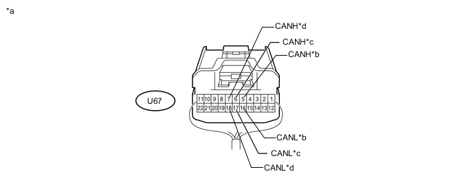
Text in Illustration *a Rear view of wire harness connector
(to No. 1 CAN Junction Connector)
*b for No. 2 CAN Junction Connector *c for ECM *d for Parking Brake ECU Assembly No. 1 CAN Junction Connector Wiring Color Connect to U67-5 (CANH) P No. 2 CAN junction connector U67-16 (CANL) W U67-6 (CANH) G ECM U67-17 (CANL) W U67-7 (CANH) B Parking brake ECU assembly U67-18 (CANL) W -
NO. 2 CAN JUNCTION CONNECTOR
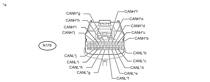
Text in Illustration *a Rear view of wire harness connector
(to No. 2 CAN Junction Connector)
*b for No. 3 CAN Junction Connector *c for Central Gateway ECU *d for Yaw Rate Sensor *e for Airbag Sensor Assembly *f for Certification ECU (Smart Key ECU Assembly) *g for Main Body ECU (Multiplex Network Body ECU) *h for No. 1 CAN Junction Connector *i for Front Steering Control ECU (w/ Variable Gear Ratio Steering System) *j for Power Steering ECU Assembly No. 2 CAN Junction Connector Wiring Color Connect to N178-1 (CANH) B No. 3 CAN junction connector N178-12 (CANL) W N178-2 (CANH) G Central gateway ECU N178-13 (CANL) W N178-3 (CANH) B Yaw rate sensor N178-14 (CANL) W N178-4 (CANH) Y Airbag sensor assembly N178-15 (CANL) W N178-5 (CANH) R Certification ECU (smart key ECU assembly) N178-16 (CANL) W N178-6 (CANH) V Main body ECU (multiplex network body ECU) N178-17 (CANL) W N178-7 (CANH) P No. 1 CAN junction connector N178-18 (CANL) W N178-8 (CANH) R Front steering control ECU* N178-19 (CANL) W N178-9 (CANH) L Power steering ECU assembly N178-20 (CANL) W
-
*: w/ Variable Gear Ratio Steering System
-
-
NO. 3 CAN JUNCTION CONNECTOR
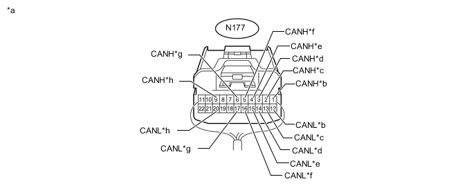
Text in Illustration *a Rear view of wire harness connector
(to No. 3 CAN Junction Connector)
*b for Skid Control ECU Assembly *c for Steering Angle Sensor *d for Power Management Control ECU *e for Combination Meter Assembly *f for Air Conditioning Amplifier Assembly *g for No. 2 CAN Junction Connector *h for Combination Meter Mirror ECU (w/ Headup Display System) No. 3 CAN Junction Connector Wiring Color Connect to N177-1 (CANH) L Skid control ECU assembly N177-12 (CANL) W N177-2 (CANH) R Steering angle sensor N177-13 (CANL) W N177-3 (CANH) P Power management control ECU N177-14 (CANL) W N177-4 (CANH) V Combination meter assembly N177-15 (CANL) W N177-5 (CANH) Y Air conditioning amplifier assembly N177-16 (CANL) W N177-6 (CANH) B No. 2 CAN junction connector N177-17 (CANL) W N177-9 (CANH) P Combination meter mirror ECU* N177-20 (CANL) R
-
*: w/ Headup Display System
-
-
NO. 4 CAN JUNCTION CONNECTOR
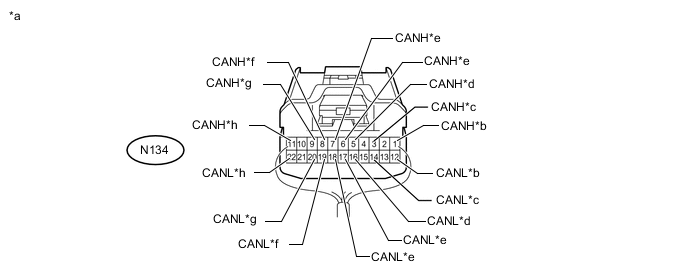
Text in Illustration *a Rear view of wire harness connector
(to No. 4 CAN Junction Connector)
*b for Skid Control ECU Assembly *c for Absorber Control ECU (w/ Adaptive Variable Suspension System) *d for No. 6 CAN Junction Connector *e for Driving Support ECU Assembly (w/ Pre-crash Safety System) *f for No. 8 CAN Junction Connector *g for Absorber Control ECU (w/ Adaptive Variable Suspension System) *h for No. 9 CAN Junction Connector No. 4 CAN Junction Connector Wiring Color Connect to N134-1 (CANH) Y Skid control ECU assembly N134-12 (CANL) SB N134-3 (CANH) L Absorber control ECU*1 N134-14 (CANL) SB N134-5 (CANH) B No. 6 CAN junction connector N134-16 (CANL) SB N134-6 (CANH) G Driving support ECU assembly*2 N134-17 (CANL) SB N134-7 (CANH) V N134-18 (CANL) LG N134-8 (CANH) V No. 8 CAN junction connector N134-19 (CANL) LG N134-9 (CANH) V Absorber control ECU*1 N134-20 (CANL) LG N134-11 (CANH) L No. 9 CAN junction connector N134-22 (CANL) LG
-
*1: w/ Adaptive Variable Suspension System
-
*2: w/ Pre-crash Safety System
-
-
NO. 5 CAN JUNCTION CONNECTOR
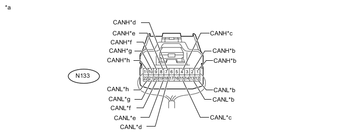
Text in Illustration *a Rear view of wire harness connector
(to No. 5 CAN Junction Connector)
*b for Central Gateway ECU *c for Multi-media Module Receiver Assembly *d for No. 10 CAN Junction Connector *e for Multiplex Tilt and Telescopic ECU *f
-
for Position Control ECU Assembly RH (except Standard Seat Type)
-
for Power Seat Switch Assembly (for Standard Seat Type)
*g for No. 2 CAN Junction Terminal *h for Front Multiplex Network Door ECU RH No. 5 CAN Junction Connector Wiring Color Connect to N133-1 (CANH) B Central gateway ECU N133-12 (CANL) W N133-2 (CANH) B Central gateway ECU N133-13 (CANL) W N133-4 (CANH) B Multi-media module receiver assembly N133-15 (CANL) W N133-7 (CANH) B No. 10 CAN junction connector N133-18 (CANL) GR N133-8 (CANH) B Multiplex tilt and telescopic ECU N133-19 (CANL) GR N133-9 (CANH) G
-
Position control ECU assembly RH*1
-
Power seat switch assembly*2
N133-20 (CANL) GR N133-10 (CANH) L No. 2 CAN junction terminal N133-21 (CANL) GR N133-11 (CANH) Y Front multiplex network door ECU RH N133-22 (CANL) GR
-
*1: except Standard Seat Type
-
*2: for Standard Seat Type
-
-
NO. 6 CAN JUNCTION CONNECTOR
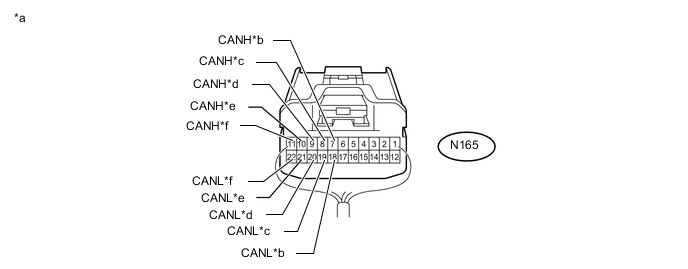
Text in Illustration *a Rear view of wire harness connector
(to No. 6 CAN Junction Connector)
*b for No. 7 CAN Junction Connector *c for Front Steering Control ECU (w/ Variable Gear Ratio Steering System) *d for Central Gateway ECU *e for No. 4 CAN Junction Connector *f for Power Steering ECU Assembly No. 6 CAN Junction Connector Wiring Color Connect to N165-7 (CANH) R No. 7 CAN junction connector N165-18 (CANL) SB N165-8 (CANH) G Front steering control ECU* N165-19 (CANL) SB N165-9 (CANH) V Central gateway ECU N165-20 (CANL) SB N165-10 (CANH) B No. 4 CAN junction connector N165-21 (CANL) SB N165-11 (CANH) Y Power steering ECU assembly N165-22 (CANL) L
-
*: w/ Variable Gear Ratio Steering System
-
-
NO. 7 CAN JUNCTION CONNECTOR
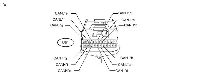
Text in Illustration *a Rear view of wire harness connector
(to No. 7 CAN Junction Connector)
*b for No. 1 CAN Junction Terminal *c for No. 6 CAN Junction Connector *d for Rear Steering Control ECU (w/ Dynamic Rear Steering System) *e for Main Body ECU (Multiplex Network Body ECU) *f for No. 10 CAN Junction Connector *g
-
for Luggage Closer Motor Assembly (w/ Power Trunk Lid System)
-
for Multiplex Network Door ECU (w/o Power Trunk Lid System)
- - No. 7 CAN Junction Connector Wiring Color Connect to U54-5 (CANH) B No. 1 CAN junction terminal U54-16 (CANL) SB U54-6 (CANH) R No. 6 CAN junction connector U54-17 (CANL) SB U54-7 (CANH) G Rear steering control ECU*1 U54-18 (CANL) SB U54-20 (CANH) R Main body ECU (multiplex network body ECU) U54-9 (CANL) GR U54-21 (CANH) L No. 10 CAN junction connector U54-10 (CANL) GR U54-22 (CANH) G
-
Luggage closer motor assembly*2
-
Multiplex network door ECU*3
U54-11 (CANL) GR
-
*1: w/ Dynamic Rear Steering System
-
*2: w/ Power Trunk Lid System
-
*3: w/o Power Trunk Lid System
-
-
NO. 8 CAN JUNCTION CONNECTOR
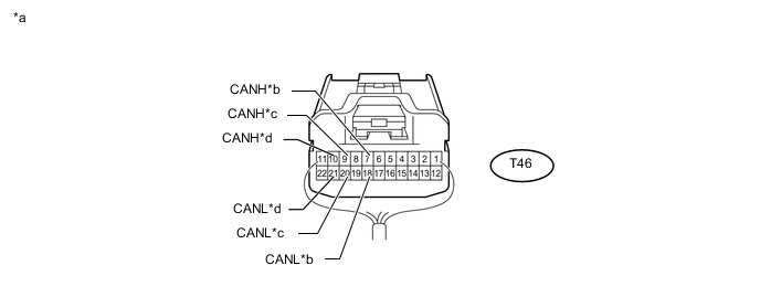
Text in Illustration *a Rear view of wire harness connector
(to No. 8 CAN Junction Connector)
*b for No. 4 CAN Junction Connector *c for Central Gateway ECU *d for Blind Spot Monitor Sensor RH (w/ Blind Spot Monitor System) No. 8 CAN Junction Connector Wiring Color Connect to T46-7 (CANH) B No. 4 CAN junction connector T46-18 (CANL) LG T46-9 (CANH) P Central gateway ECU T46-20 (CANL) LG T46-10 (CANH) L Blind spot monitor sensor RH* T46-21 (CANL) LG
-
*: w/ Blind Spot Monitor System
-
-
NO. 9 CAN JUNCTION CONNECTOR
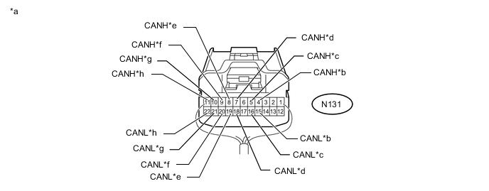
Text in Illustration *a Rear view of wire harness connector
(to No. 9 CAN Junction Connector)
*b for Central Gateway ECU *c for No. 4 CAN Junction Connector *d for Power Management Control ECU *e for Headlight ECU Sub-assembly LH *f for Clearance Warning ECU Assembly (w/ LEXUS Parking Assist-sensor System) *g for Forward Recognition Camera (w/ Pre-crash Safety System) *h for Millimeter Wave Radar Sensor Assembly (w/ Pre-crash Safety System) No. 9 CAN Junction Connector Wiring Color Connect to N131-4 (CANH) L Central gateway ECU N131-15 (CANL) LG N131-5 (CANH) L No. 4 CAN junction connector N131-16 (CANL) LG N131-7 (CANH) L Power management control ECU N131-18 (CANL) LG N131-8 (CANH) L Headlight ECU sub-assembly LH N131-19 (CANL) LG N131-9 (CANH) L Clearance warning ECU assembly*2 N131-20 (CANL) LG N131-10 (CANH) L Forward recognition camera*1 N131-21 (CANL) LG N131-11 (CANH) L Millimeter wave radar sensor assembly*1 N131-22 (CANL) LG
-
*1: w/ Pre-crash Safety System
-
*2: w/ LEXUS Parking Assist-sensor System
-
-
NO. 10 CAN JUNCTION CONNECTOR
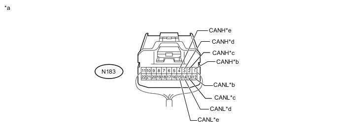
Text in Illustration *a Rear view of wire harness connector
(to No. 10 CAN Junction Connector)
*b for No. 5 CAN Junction Connector *c for Position Control ECU Assembly LH (for Luxury Seat Type) *d for No. 7 CAN Junction Connector *e for Front Multiplex Network Door ECU LH - - No. 10 CAN Junction Connector Wiring Color Connect to N183-1 (CANH) B No. 5 CAN junction connector N183-12 (CANL) GR N183-2 (CANH) G Position control ECU assembly LH* N183-13 (CANL) GR N183-3 (CANH) L No. 7 CAN junction connector N183-14 (CANL) GR N183-4 (CANH) Y Front multiplex network door ECU LH N183-15 (CANL) GR
-
*: for Luxury Seat Type
-
-
NO. 11 CAN JUNCTION CONNECTOR
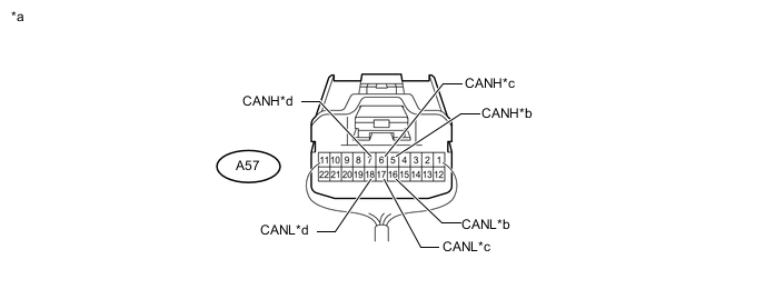
Text in Illustration *a Rear view of wire harness connector
(to No. 11 CAN Junction Connector)
*b for ECM *c for Power Management Control ECU *d for Skid Control ECU Assembly No. 11 CAN Junction Connector Wiring Color Connect to A57-5 (CANH) B*1, W*2 ECM A57-16 (CANL) W*1, B*2 A57-6 (CANH) B Power management control ECU A57-17 (CANL) W A57-7 (CANH) G Skid control ECU assembly A57-18 (CANL) W
-
*1: for 2GR-FXE
-
*2: for 2AR-FSE
-
-
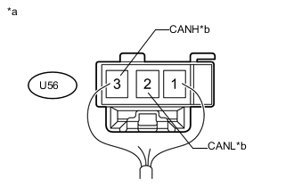
Text in Illustration *a Rear view of wire harness connector
(to No. 1 CAN Junction Terminal)
*b for No. 7 CAN Junction Connector NO. 1 CAN JUNCTION TERMINAL
No. 1 CAN Junction Terminal Wiring Color Connect to U56-2 (CANL) SB No. 7 CAN junction connector U56-3 (CANH) B -
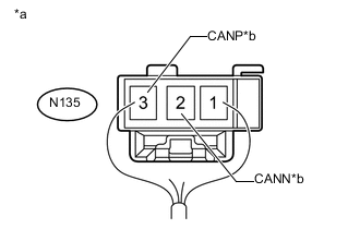
Text in Illustration *a Rear view of wire harness connector
(to No. 2 CAN Junction Terminal)
*b for No. 5 CAN Junction Connector NO. 2 CAN JUNCTION TERMINAL
No. 2 CAN Junction Terminal Wiring Color Connect to N135-2 (CANN) GR No. 5 CAN junction connector N135-3 (CANP) L
-
-
CHECK DLC3
-
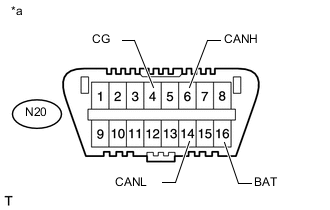
Text in Illustration *a Front view of DLC3 Disconnect the cable from the negative (-) auxiliary battery terminal before measuring the resistances of the CAN main wire and CAN branch wire.
-
Measure the resistance according to the value(s) in the table below.
Terminal No. (Symbol) Wiring Color Terminal Description Condition Specified Condition N20-6 (CANH) - N20-14 (CANL) P - V HIGH-level CAN bus line - LOW-level CAN bus line Cable disconnected from negative (-) auxiliary battery terminal 54 to 66 Ω N20-6 (CANH) - N20-4 (CG) P - W-B HIGH-level CAN bus line - Ground Cable disconnected from negative (-) auxiliary battery terminal 200 Ω or higher N20-14 (CANL) - N20-4 (CG) V - W-B LOW-level CAN bus line - Ground Cable disconnected from negative (-) auxiliary battery terminal 200 Ω or higher N20-6 (CANH) - N20-16 (BAT) P - W HIGH-level CAN bus line - auxiliary battery positive (+) Cable disconnected from negative (-) auxiliary battery terminal 6 kΩ or higher N20-14 (CANL) - N20-16 (BAT) V - W LOW-level CAN bus line - auxiliary battery positive (+) Cable disconnected from negative (-) auxiliary battery terminal 6 kΩ or higher
-
-
CHECK CENTRAL GATEWAY ECU
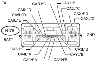
Text in Illustration *A Bus 2 *B Bus 3 *C Bus 4 *D Bus 5 *E V Bus - - *a Component without harness connected
(Central Gateway ECU)
- -
-
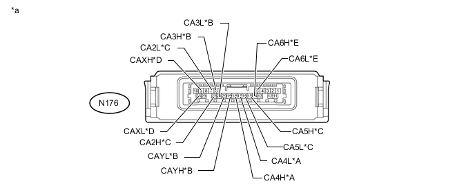
Text in Illustration *A Bus 2 *B Bus 3 *C Bus 4 *D Bus 5 *E V Bus *a Front view of wire harness connector
(to Central Gateway ECU)
Disconnect the central gateway ECU connector.
-
Measure the resistance according to the value(s) in the table below.
Bus 2 Terminal No. (Symbol) Wiring Color Terminal Description Switch Condition Specified Condition N176-18 (CA4H) - N176-17 (CA4L) G - W HIGH-level CAN bus line - LOW-level CAN bus line Cable disconnected from negative (-) auxiliary battery terminal 54 to 69 Ω N176-18 (CA4H) - N176-10 (GND) G - W-B HIGH-level CAN bus line - Ground Cable disconnected from negative (-) auxiliary battery terminal 200 Ω or higher N176-17 (CA4L) - N176-10 (GND) W - W-B LOW-level CAN bus line - Ground Cable disconnected from negative (-) auxiliary battery terminal 200 Ω or higher N176-18 (CA4H) - N176-1 (BATT) G - P HIGH-level CAN bus line - Battery positive (+) Cable disconnected from negative (-) auxiliary battery terminal 6 kΩ or higher N176-17 (CA4L) - N176-1 (BATT) W - P LOW-level CAN bus line - Battery positive (+) Cable disconnected from negative (-) auxiliary battery terminal 6 kΩ or higher Bus 3 Terminal No. (Symbol) Wiring Color Terminal Description Switch Condition Specified Condition N176-6 (CA3H) - N176-21 (CA3L) B - W HIGH-level CAN bus line - LOW-level CAN bus line Cable disconnected from negative (-) auxiliary battery terminal 200 Ω or higher N176-6 (CA3H) - N176-10 (GND) B - W-B HIGH-level CAN bus line - Ground Cable disconnected from negative (-) auxiliary battery terminal 200 Ω or higher N176-21 (CA3L) - N176-10 (GND) W - W-B LOW-level CAN bus line - Ground Cable disconnected from negative (-) auxiliary battery terminal 200 Ω or higher N176-6 (CA3H) - N176-1 (BATT) B - P HIGH-level CAN bus line - Battery positive (+) Cable disconnected from negative (-) auxiliary battery terminal 6 kΩ or higher N176-21 (CA3L) - N176-1 (BATT) W - P LOW-level CAN bus line - Battery positive (+) Cable disconnected from negative (-) auxiliary battery terminal 6 kΩ or higher Bus 3 Terminal No. (Symbol) Wiring Color Terminal Description Switch Condition Specified Condition N176-19 (CAYH) - N176-20 (CAYL) B - W HIGH-level CAN bus line - LOW-level CAN bus line Cable disconnected from negative (-) auxiliary battery terminal 200 Ω or higher N176-19 (CAYH) - N176-10 (GND) B - W-B HIGH-level CAN bus line - Ground Cable disconnected from negative (-) auxiliary battery terminal 200 Ω or higher N176-20 (CAYL) - N176-10 (GND) W - W-B LOW-level CAN bus line - Ground Cable disconnected from negative (-) auxiliary battery terminal 200 Ω or higher N176-19 (CAYH) - N176-1 (BATT) B - P HIGH-level CAN bus line - Battery positive (+) Cable disconnected from negative (-) auxiliary battery terminal 6 kΩ or higher N176-20 (CAYL) - N176-1 (BATT) W - P LOW-level CAN bus line - Battery positive (+) Cable disconnected from negative (-) auxiliary battery terminal 6 kΩ or higher Bus 4 Terminal No. (Symbol) Wiring Color Terminal Description Switch Condition Specified Condition N176-22 (CA2H) - N176-7 (CA2L) V - SB HIGH-level CAN bus line - LOW-level CAN bus line Cable disconnected from negative (-) auxiliary battery terminal 54 to 69 Ω N176-22 (CA2H) - N176-10 (GND) V - W-B HIGH-level CAN bus line - Ground Cable disconnected from negative (-) auxiliary battery terminal 200 Ω or higher N176-7 (CA2L) - N176-10 (GND) SB - W-B LOW-level CAN bus line - Ground Cable disconnected from negative (-) auxiliary battery terminal 200 Ω or higher N176-22 (CA2H) - N176-1 (BATT) V - P HIGH-level CAN bus line - Battery positive (+) Cable disconnected from negative (-) auxiliary battery terminal 6 kΩ or higher N176-7 (CA2L) - N176-1 (BATT) SB - P LOW-level CAN bus line - Battery positive (+) Cable disconnected from negative (-) auxiliary battery terminal 6 kΩ or higher Bus 5 Terminal No. (Symbol) Wiring Color Terminal Description Switch Condition Specified Condition N176-15 (CA5H) - N176-16 (CA5L) L - LG HIGH-level CAN bus line - LOW-level CAN bus line Cable disconnected from negative (-) auxiliary battery terminal 200 Ω or higher N176-15 (CA5H) - N176-10 (GND) L - W-B HIGH-level CAN bus line - Ground Cable disconnected from negative (-) auxiliary battery terminal 200 Ω or higher N176-16 (CA5L) - N176-10 (GND) LG - W-B LOW-level CAN bus line - Ground Cable disconnected from negative (-) auxiliary battery terminal 200 Ω or higher N176-15 (CA5H) - N176-1 (BATT) L - P HIGH-level CAN bus line - Battery positive (+) Cable disconnected from negative (-) auxiliary battery terminal 6 kΩ or higher N176-16 (CA5L) - N176-1 (BATT) LG - P LOW-level CAN bus line - Battery positive (+) Cable disconnected from negative (-) auxiliary battery terminal 6 kΩ or higher Bus 5 Terminal No. (Symbol) Wiring Color Terminal Description Switch Condition Specified Condition N176-9 (CAXH) - N176-24 (CAXL) P - LG HIGH-level CAN bus line - LOW-level CAN bus line Cable disconnected from negative (-) auxiliary battery terminal 200 Ω or higher N176-9 (CAXH) - N176-10 (GND) P - W-B HIGH-level CAN bus line - Ground Cable disconnected from negative (-) auxiliary battery terminal 200 Ω or higher N176-24 (CAXL) - N176-10 (GND) LG - W-B LOW-level CAN bus line - Ground Cable disconnected from negative (-) auxiliary battery terminal 200 Ω or higher N176-9 (CAXH) - N176-1 (BATT) P - P HIGH-level CAN bus line - Battery positive (+) Cable disconnected from negative (-) auxiliary battery terminal 6 kΩ or higher N176-24 (CAXL) - N176-1 (BATT) LG - P LOW-level CAN bus line - Battery positive (+) Cable disconnected from negative (-) auxiliary battery terminal 6 kΩ or higher V Bus Terminal No. (Symbol) Wiring Color Terminal Description Switch Condition Specified Condition N176-14 (CA6H) - N176-10 (GND) P - W-B HIGH-level CAN bus line - Ground Cable disconnected from negative (-) auxiliary battery terminal 200 Ω or higher N176-5 (CA6L) - N176-10 (GND) V - W-B LOW-level CAN bus line - Ground Cable disconnected from negative (-) auxiliary battery terminal 200 Ω or higher N176-14 (CA6H) - N176-1 (BATT) P - P HIGH-level CAN bus line - Battery positive (+) Cable disconnected from negative (-) auxiliary battery terminal 6 kΩ or higher N176-5 (CA6L) - N176-1 (BATT) V - P LOW-level CAN bus line - Battery positive (+) Cable disconnected from negative (-) auxiliary battery terminal 6 kΩ or higher
-
-
CHECK ECM (for 2GR-FXE)
-
Terminal Connector Click here.
-
Disconnect the ECM connectors.
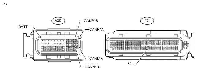
Text in Illustration *A Bus 2 *B Sub Bus 15 *a Front view of wire harness connector
(to ECM)
- - -
Measure the resistance according to the value(s) in the table below.
Bus 2 Terminal No. (Symbol) Wiring Color Terminal Description Condition Specified Condition A20-13 (CANH) - A20-26 (CANL) G - W HIGH-level CAN bus line - LOW-level CAN bus line Cable disconnected from negative (-) auxiliary battery terminal 108 to 132 Ω A20-13 (CANH) - F5-49 (E1) G - BR HIGH-level CAN bus line - Ground Cable disconnected from negative (-) auxiliary battery terminal 200 Ω or higher A20-26 (CANL) - F5-49 (E1) W - BR LOW-level CAN bus line - Ground Cable disconnected from negative (-) auxiliary battery terminal 200 Ω or higher A20-13 (CANH) - A20-1 (BATT) G - L HIGH-level CAN bus line - auxiliary battery positive (+) Cable disconnected from negative (-) auxiliary battery terminal 6 kΩ or higher A20-26 (CANL) - A20-1 (BATT) W - L LOW-level CAN bus line - auxiliary battery positive (+) Cable disconnected from negative (-) auxiliary battery terminal 6 kΩ or higher Sub Bus 15 Terminal No. (Symbol) Wiring Color Terminal Description Condition Specified Condition A20-12 (CANP) - A20-25 (CANN) B - W HIGH-level CAN bus line - LOW-level CAN bus line Cable disconnected from negative (-) auxiliary battery terminal 108 to 132 Ω A20-12 (CANP) - F5-49 (E1) B - BR HIGH-level CAN bus line - Ground Cable disconnected from negative (-) auxiliary battery terminal 200 Ω or higher A20-25 (CANN) - F5-49 (E1) W - BR LOW-level CAN bus line - Ground Cable disconnected from negative (-) auxiliary battery terminal 200 Ω or higher A20-12 (CANP) - A20-1 (BATT) B - L HIGH-level CAN bus line - auxiliary battery positive (+) Cable disconnected from negative (-) auxiliary battery terminal 6 kΩ or higher A20-25 (CANN) - A20-1 (BATT) W - L LOW-level CAN bus line - auxiliary battery positive (+) Cable disconnected from negative (-) auxiliary battery terminal 6 kΩ or higher
-
-
CHECK ECM (for 2AR-FSE)
-
Terminal Connector.
-
w/ EGR System: Click here
-
w/o EGR System: Click here
-
-
Disconnect the ECM connectors.
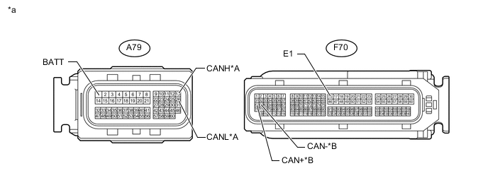
Text in Illustration *A Bus 2 *B Sub Bus 15 *a Front view of wire harness connector
(to ECM)
- - -
Measure the resistance according to the value(s) in the table below.
Bus 2 Terminal No. (Symbol) Wiring Color Terminal Description Condition Specified Condition A79-13 (CANH) - A79-26 (CANL) G - W HIGH-level CAN bus line - LOW-level CAN bus line Cable disconnected from negative (-) auxiliary battery terminal 108 to 132 Ω A79-13 (CANH) - F70-16 (E1) G - BR HIGH-level CAN bus line - Ground Cable disconnected from negative (-) auxiliary battery terminal 200 Ω or higher A79-26 (CANL) - F70-16 (E1) W - BR LOW-level CAN bus line - Ground Cable disconnected from negative (-) auxiliary battery terminal 200 Ω or higher A79-13 (CANH) - A79-1 (BATT) G - L HIGH-level CAN bus line - auxiliary battery positive (+) Cable disconnected from negative (-) auxiliary battery terminal 6 kΩ or higher A79-26 (CANL) - A79-1 (BATT) W - L LOW-level CAN bus line - auxiliary battery positive (+) Cable disconnected from negative (-) auxiliary battery terminal 6 kΩ or higher Sub Bus 15 Terminal No. (Symbol) Wiring Color Terminal Description Condition Specified Condition F70-61 (CAN+) - F70-62 (CAN-) G - W HIGH-level CAN bus line - LOW-level CAN bus line Cable disconnected from negative (-) auxiliary battery terminal 108 to 132 Ω F70-61 (CAN+) - F70-16 (E1) G - BR HIGH-level CAN bus line - Ground Cable disconnected from negative (-) auxiliary battery terminal 200 Ω or higher F70-62 (CAN-) - F70-16 (E1) W - BR LOW-level CAN bus line - Ground Cable disconnected from negative (-) auxiliary battery terminal 200 Ω or higher F70-61 (CAN+) - A79-1 (BATT) G - L HIGH-level CAN bus line - auxiliary battery positive (+) Cable disconnected from negative (-) auxiliary battery terminal 6 kΩ or higher F70-62 (CAN-) - A79-1 (BATT) W - L LOW-level CAN bus line - auxiliary battery positive (+) Cable disconnected from negative (-) auxiliary battery terminal 6 kΩ or higher
-
-
CHECK POWER MANAGEMENT CONTROL ECU
-
Terminal Connector.
-
for 2GR-FXE: Click here
-
for 2AR-FSE: Click here
-
-
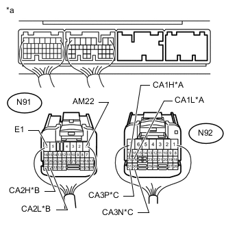
Text in Illustration *A Bus 2 *B Bus 5 *C Sub Bus 15 *a Rear view of wire harness connector
(to Power Management Control ECU)
Disconnect the power management control ECU connectors.
-
Measure the resistance according to the value(s) in the table below.
Bus 2 Terminal No. (Symbol) Wiring Color Terminal Description Condition Specified Condition N92-25 (CA1H) - N92-24 (CA1L) P - W HIGH-level CAN bus line - LOW-level CAN bus line Cable disconnected from negative (-) auxiliary battery terminal 108 to 132 Ω N92-25 (CA1H) - N91-6 (E1) P - W-B HIGH-level CAN bus line - Ground Cable disconnected from negative (-) auxiliary battery terminal 200 Ω or higher N92-24 (CA1L) - N91-6 (E1) W - W-B LOW-level CAN bus line - Ground Cable disconnected from negative (-) auxiliary battery terminal 200 Ω or higher N92-25 (CA1H) - N91-1 (AM22) P - P HIGH-level CAN bus line - auxiliary battery positive (+) Cable disconnected from negative (-) auxiliary battery terminal 6 kΩ or higher N92-24 (CA1L) - N91-1 (AM22) W - P LOW-level CAN bus line - auxiliary battery positive (+) Cable disconnected from negative (-) auxiliary battery terminal 6 kΩ or higher Bus 5 Terminal No. (Symbol) Wiring Color Terminal Description Condition Specified Condition N91-35 (CA2H) - N91-34 (CA2L) V - LG HIGH-level CAN bus line - LOW-level CAN bus line Cable disconnected from negative (-) auxiliary battery terminal 54 to 69 Ω N91-35 (CA2H) - N91-6 (E1) V - W-B HIGH-level CAN bus line - Ground Cable disconnected from negative (-) auxiliary battery terminal 200 Ω or higher N91-34 (CA2L) - N91-6 (E1) LG - W-B LOW-level CAN bus line - Ground Cable disconnected from negative (-) auxiliary battery terminal 200 Ω or higher N91-35 (CA2H) - N91-1 (AM22) V - P HIGH-level CAN bus line - auxiliary battery positive (+) Cable disconnected from negative (-) auxiliary battery terminal 6 kΩ or higher N91-34 (CA2L) - N91-1 (AM22) LG - P LOW-level CAN bus line - auxiliary battery positive (+) Cable disconnected from negative (-) auxiliary battery terminal 6 kΩ or higher Sub Bus 15 Terminal No. (Symbol) Wiring Color Terminal Description Condition Specified Condition N92-31 (CA3P) - N92-30 (CA3N) R - W HIGH-level CAN bus line - LOW-level CAN bus line Cable disconnected from negative (-) auxiliary battery terminal 108 to 132 Ω N92-31 (CA3P) - N91-6 (E1) R - W-B HIGH-level CAN bus line - Ground Cable disconnected from negative (-) auxiliary battery terminal 200 Ω or higher N92-30 (CA3N) - N91-6 (E1) W - W-B LOW-level CAN bus line - Ground Cable disconnected from negative (-) auxiliary battery terminal 200 Ω or higher N92-31 (CA3P) - N91-1 (AM22) R - P HIGH-level CAN bus line - auxiliary battery positive (+) Cable disconnected from negative (-) auxiliary battery terminal 6 kΩ or higher N92-30 (CA3N) - N91-1 (AM22) W - P LOW-level CAN bus line - auxiliary battery positive (+) Cable disconnected from negative (-) auxiliary battery terminal 6 kΩ or higher
-
-
CHECK SKID CONTROL ECU ASSEMBLY
-
Terminal Connector Click here.
-
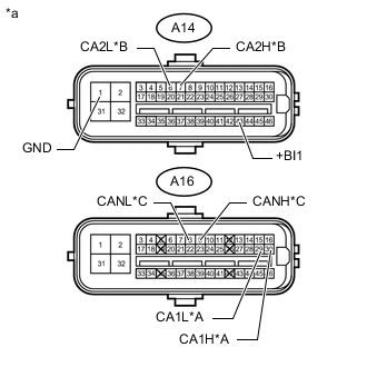
Text in Illustration *A Bus 2 *B Bus 4 *C Sub Bus 15 *a Front view of wire harness connector
(to Skid Control ECU Assembly)
Disconnect the skid control ECU assembly connectors.
-
Measure the resistance according to the value(s) in the table below.
Bus 2 Terminal No. (Symbol) Wiring Color Terminal Description Condition Specified Condition A16-30 (CA1H) - A16-29 (CA1L) L - W HIGH-level CAN bus line - LOW-level CAN bus line Cable disconnected from negative (-) auxiliary battery terminal 54 to 69 Ω A16-30 (CA1H) - A14-1 (GND) L - W-B HIGH-level CAN bus line - Ground Cable disconnected from negative (-) auxiliary battery terminal 200 Ω or higher A16-29 (CA1L) - A14-1 (GND) W - W-B LOW-level CAN bus line - Ground Cable disconnected from negative (-) auxiliary battery terminal 200 Ω or higher A16-30 (CA1H) - A14-43 (+BI1) L - L HIGH-level CAN bus line - auxiliary battery positive (+) Cable disconnected from negative (-) auxiliary battery terminal 6 kΩ or higher A16-29 (CA1L) - A14-43 (+BI1) W - L LOW-level CAN bus line - auxiliary battery positive (+) Cable disconnected from negative (-) auxiliary battery terminal 6 kΩ or higher Bus 4 Terminal No. (Symbol) Wiring Color Terminal Description Condition Specified Condition A14-7 (CA2H) - A14-6 (CA2L) R - SB HIGH-level CAN bus line - LOW-level CAN bus line Cable disconnected from negative (-) auxiliary battery terminal 108 to 132 Ω A14-7 (CA2H) - A14-1 (GND) R - W-B HIGH-level CAN bus line - Ground Cable disconnected from negative (-) auxiliary battery terminal 200 Ω or higher A14-6 (CA2L) - A14-1 (GND) SB - W-B LOW-level CAN bus line - Ground Cable disconnected from negative (-) auxiliary battery terminal 200 Ω or higher A14-7 (CA2H) - A14-43 (+BI1) R - L HIGH-level CAN bus line - auxiliary battery positive (+) Cable disconnected from negative (-) auxiliary battery terminal 6 kΩ or higher A14-6 (CA2L) - A14-43 (+BI1) SB - L LOW-level CAN bus line - auxiliary battery positive (+) Cable disconnected from negative (-) auxiliary battery terminal 6 kΩ or higher Sub Bus 15 Terminal No. (Symbol) Wiring Color Terminal Description Condition Specified Condition A16-9 (CANH) - A16-8 (CANL) G - W HIGH-level CAN bus line - LOW-level CAN bus line Cable disconnected from negative (-) auxiliary battery terminal 54 to 69 Ω A16-9 (CANH) - A14-1 (GND) G - W-B HIGH-level CAN bus line - Ground Cable disconnected from negative (-) auxiliary battery terminal 200 Ω or higher A16-8 (CANL) - A14-1 (GND) W - W-B LOW-level CAN bus line - Ground Cable disconnected from negative (-) auxiliary battery terminal 200 Ω or higher A16-9 (CANH) - A14-43 (+BI1) G - L HIGH-level CAN bus line - auxiliary battery positive (+) Cable disconnected from negative (-) auxiliary battery terminal 6 kΩ or higher A16-8 (CANL) - A14-43 (+BI1) W - L LOW-level CAN bus line - auxiliary battery positive (+) Cable disconnected from negative (-) auxiliary battery terminal 6 kΩ or higher
-
-
CHECK CERTIFICATION ECU (SMART KEY ECU ASSEMBLY)
-
Terminal Connector Click here.
-
Disconnect the certification ECU (smart key ECU assembly) connectors.
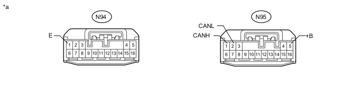
Text in Illustration *a Front view of wire harness connector
(to Certification ECU [Smart Key ECU Assembly])
- - -
Measure the resistance according to the value(s) in the table below.
Terminal No. (Symbol) Wiring Color Terminal Description Condition Specified Condition N95-1 (CANH) - N95-2 (CANL) R - W HIGH-level CAN bus line - LOW-level CAN bus line Cable disconnected from negative (-) auxiliary battery terminal 54 to 69 Ω N95-1 (CANH) - N94-1 (E) R - W-B HIGH-level CAN bus line - Ground Cable disconnected from negative (-) auxiliary battery terminal 200 Ω or higher N95-2 (CANL) - N94-1 (E) W - W-B LOW-level CAN bus line - Ground Cable disconnected from negative (-) auxiliary battery terminal 200 Ω or higher N95-1 (CANH) - N95-5 (+B) R - W HIGH-level CAN bus line - Battery positive (+) Cable disconnected from negative (-) auxiliary battery terminal 6 kΩ or higher N95-2 (CANL) - N95-5 (+B) W - W LOW-level CAN bus line - Battery positive (+) Cable disconnected from negative (-) auxiliary battery terminal 6 kΩ or higher
-
-
CHECK COWL SIDE JUNCTION BLOCK LH AND MAIN BODY ECU (MULTIPLEX NETWORK BODY ECU)
-
Terminal Connector Click here.
-
Remove the main body ECU (multiplex network body ECU) from the cowl side junction block LH Click here.
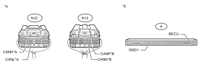
Text in Illustration *A Bus 2 *B Sub Bus 1 *a Rear view of wire harness connector
(to Cowl Side Junction Block LH)
*b Front view of wire harness connector
(to Main Body ECU [Multiplex Network Body ECU])
-
Reconnect the cowl side junction block LH connectors.
-
Measure the resistance according to the value(s) in the table below.
Bus 2 Terminal No. (Symbol) Wiring Color Terminal Description Condition Specified Condition N12-14 (CANH) - N12-13 (CANL) V - W HIGH-level CAN bus line - LOW-level CAN bus line Cable disconnected from negative (-) auxiliary battery terminal 54 to 69 Ω N12-14 (CANH) - A-11 (GND1) V - None HIGH-level CAN bus line - Ground Cable disconnected from negative (-) auxiliary battery terminal 200 Ω or higher N12-13 (CANL) - A-11 (GND1) W - None LOW-level CAN bus line - Ground Cable disconnected from negative (-) auxiliary battery terminal 200 Ω or higher N12-14 (CANH) - A-30 (BECU) V - None HIGH-level CAN bus line - auxiliary battery positive (+) Cable disconnected from negative (-) auxiliary battery terminal 6 kΩ or higher N12-13 (CANL) - A-30 (BECU) W - None LOW-level CAN bus line - auxiliary battery positive (+) Cable disconnected from negative (-) auxiliary battery terminal 6 kΩ or higher Sub Bus 1 Terminal No. (Symbol) Wiring Color Terminal Description Condition Specified Condition N13-9 (CANP) - N13-10 (CANN) R - GR HIGH-level CAN bus line - LOW-level CAN bus line Cable disconnected from negative (-) auxiliary battery terminal 108 to 132 Ω N13-9 (CANP) - A-11 (GND1) R - None HIGH-level CAN bus line - Ground Cable disconnected from negative (-) auxiliary battery terminal 200 Ω or higher N13-10 (CANN) - A-11 (GND1) GR - None LOW-level CAN bus line - Ground Cable disconnected from negative (-) auxiliary battery terminal 200 Ω or higher N13-9 (CANP) - A-30 (BECU) R - None HIGH-level CAN bus line - auxiliary battery positive (+) Cable disconnected from negative (-) auxiliary battery terminal 6 kΩ or higher N13-10 (CANN) - A-30 (BECU) GR - None LOW-level CAN bus line - auxiliary battery positive (+) Cable disconnected from negative (-) auxiliary battery terminal 6 kΩ or higher
-
-
CHECK PARKING BRAKE ECU ASSEMBLY
-
Terminal Connector Click here.
-
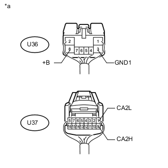
Text in Illustration *a Rear view of wire harness connector
(to Parking Brake ECU Assembly)
Disconnect the parking brake ECU assembly connectors.
-
Measure the resistance according to the value(s) in the table below.
Terminal No. (Symbol) Wiring Color Terminal Description Condition Specified Condition U37-9 (CA2H) - U37-1 (CA2L) B - W HIGH-level CAN bus line - LOW-level CAN bus line Cable disconnected from negative (-) auxiliary battery terminal 54 to 69 Ω U37-9 (CA2H) - U36-3 (GND1) B - W-B HIGH-level CAN bus line - Ground Cable disconnected from negative (-) auxiliary battery terminal 200 Ω or higher U37-1 (CA2L) - U36-3 (GND1) W - W-B LOW-level CAN bus line - Ground Cable disconnected from negative (-) auxiliary battery terminal 200 Ω or higher U37-9 (CA2H) - U36-8 (+B) B - B HIGH-level CAN bus line - auxiliary battery positive (+) Cable disconnected from negative (-) auxiliary battery terminal 6 kΩ or higher U37-1 (CA2L) - U36-8 (+B) W - B LOW-level CAN bus line - auxiliary battery positive (+) Cable disconnected from negative (-) auxiliary battery terminal 6 kΩ or higher
-
-
CHECK POWER STEERING ECU ASSEMBLY
-
Terminal Connector.
-
for 2GR-FXE: Click here
-
for 2AR-FSE: Click here
-
-
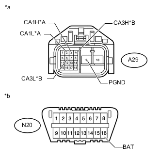
Text in Illustration *A Bus 2 *B Bus 4 *a Front view of wire harness connector
(to Power Steering ECU Assembly)
*b Front view of DLC3 Disconnect the power steering ECU assembly connector.
-
Measure the resistance according to the value(s) in the table below.
Bus 2 Terminal No. (Symbol) Wiring Color Terminal Description Condition Specified Condition A29-3 (CA1H) - A29-2 (CA1L) W - B HIGH-level CAN bus line - LOW-level CAN bus line Cable disconnected from negative (-) auxiliary battery terminal 54 to 69 Ω A29-3 (CA1H) - A29-9 (PGND) W - B HIGH-level CAN bus line - Ground Cable disconnected from negative (-) auxiliary battery terminal 200 Ω or higher A29-2 (CA1L) - A29-9 (PGND) B - B LOW-level CAN bus line - Ground Cable disconnected from negative (-) auxiliary battery terminal 200 Ω or higher A29-3 (CA1H) - N20-16 (BAT) W - W HIGH-level CAN bus line - auxiliary battery positive (+) Cable disconnected from negative (-) auxiliary battery terminal 6 kΩ or higher A29-2 (CA1L) - N20-16 (BAT) B - W LOW-level CAN bus line - auxiliary battery positive (+) Cable disconnected from negative (-) auxiliary battery terminal 6 kΩ or higher Bus 4 Terminal No. (Symbol) Wiring Color Terminal Description Condition Specified Condition A29-4 (CA3H) - A29-6 (CA3L) Y - L HIGH-level CAN bus line - LOW-level CAN bus line Cable disconnected from negative (-) auxiliary battery terminal 54 to 69 Ω A29-4 (CA3H) - A29-9 (PGND) Y - B HIGH-level CAN bus line - Ground Cable disconnected from negative (-) auxiliary battery terminal 200 Ω or higher A29-6 (CA3L) - A29-9 (PGND) L - B LOW-level CAN bus line - Ground Cable disconnected from negative (-) auxiliary battery terminal 200 Ω or higher A29-4 (CA3H) - N20-16 (BAT) Y - W HIGH-level CAN bus line - auxiliary battery positive (+) Cable disconnected from negative (-) auxiliary battery terminal 6 kΩ or higher A29-6 (CA3L) - N20-16 (BAT) L - W LOW-level CAN bus line - auxiliary battery positive (+) Cable disconnected from negative (-) auxiliary battery terminal 6 kΩ or higher
-
-
CHECK AIR CONDITIONING AMPLIFIER ASSEMBLY
-
Terminal Connector Click here.
-
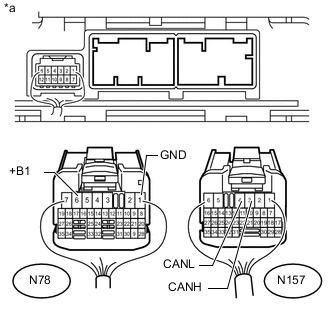
Text in Illustration *a Rear view of wire harness connector
(to Air Conditioning Amplifier Assembly)
Disconnect the air conditioning amplifier assembly connectors.
-
Measure the resistance according to the value(s) in the table below.
Terminal No. (Symbol) Wiring Color Terminal Description Condition Specified Condition N157-3 (CANH) - N157-4 (CANL) Y - W HIGH-level CAN bus line - LOW-level CAN bus line Cable disconnected from negative (-) auxiliary battery terminal 54 to 69 Ω N157-3 (CANH) - N78-1 (GND) Y - W-B HIGH-level CAN bus line - Ground Cable disconnected from negative (-) auxiliary battery terminal 200 Ω or higher N157-4 (CANL) - N78-1 (GND) W - W-B LOW-level CAN bus line - Ground Cable disconnected from negative (-) auxiliary battery terminal 200 Ω or higher N157-3 (CANH) - N78-6 (+B1) Y - W HIGH-level CAN bus line - Battery positive (+) Cable disconnected from negative (-) auxiliary battery terminal 6 kΩ or higher N157-4 (CANL) - N78-6 (+B1) W - W LOW-level CAN bus line - Battery positive (+) Cable disconnected from negative (-) auxiliary battery terminal 6 kΩ or higher
-
-
CHECK MULTI-MEDIA MODULE RECEIVER ASSEMBLY
-
Terminal Connector Click here.
-
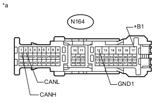
Text in Illustration *a Front view of wire harness connector
(to Multi-media Module Receiver Assembly)
Disconnect the multi-media module receiver assembly connector.
-
Measure the resistance according to the value(s) in the table below.
Terminal No. (Symbol) Wiring Color Terminal Description Condition Specified Condition N164-1 (CANH) - N164-2 (CANL) B - W HIGH-level CAN bus line - LOW-level CAN bus line Cable disconnected from negative (-) auxiliary battery terminal 54 to 69 Ω N164-1 (CANH) - N164-12 (GND1) B - W-B HIGH-level CAN bus line - Ground Cable disconnected from negative (-) auxiliary battery terminal 200 Ω or higher N164-2 (CANL) - N164-12 (GND1) W - W-B LOW-level CAN bus line - Ground Cable disconnected from negative (-) auxiliary battery terminal 200 Ω or higher N164-1 (CANH) - N164-17 (+B1) B - L HIGH-level CAN bus line - Battery positive (+) Cable disconnected from negative (-) auxiliary battery terminal 6 kΩ or higher N164-2 (CANL) - N164-17 (+B1) W - L LOW-level CAN bus line - Battery positive (+) Cable disconnected from negative (-) auxiliary battery terminal 6 kΩ or higher
-
-
CHECK COMBINATION METER ASSEMBLY
-
Terminal Connector Click here.
-
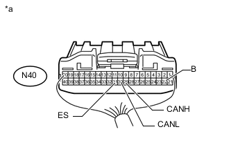
Text in Illustration *a Rear view of wire harness connector
(to Combination Meter Assembly)
Disconnect the combination meter assembly connector.
-
Measure the resistance according to the value(s) in the table below.
Terminal No. (Symbol) Wiring Color Terminal Description Condition Specified Condition N40-29 (CANH) - N40-30 (CANL) V - W HIGH-level CAN bus line - LOW-level CAN bus line Cable disconnected from negative (-) auxiliary battery terminal 54 to 69 Ω N40-29 (CANH) - N40-31 (ES) V - W-B HIGH-level CAN bus line - Ground Cable disconnected from negative (-) auxiliary battery terminal 200 Ω or higher N40-30 (CANL) - N40-31 (ES) W - W-B LOW-level CAN bus line - Ground Cable disconnected from negative (-) auxiliary battery terminal 200 Ω or higher N40-29 (CANH) - N40-22 (B) V - P HIGH-level CAN bus line - Battery positive (+) Cable disconnected from negative (-) auxiliary battery terminal 6 kΩ or higher N40-30 (CANL) - N40-22 (B) W - P LOW-level CAN bus line - Battery positive (+) Cable disconnected from negative (-) auxiliary battery terminal 6 kΩ or higher
-
-
CHECK AIRBAG SENSOR ASSEMBLY
-
Terminal Connector Click here.
-
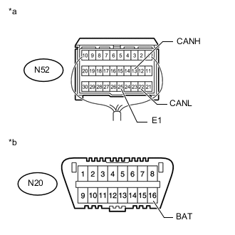
Text in Illustration *a Rear view of wire harness connector
(to Airbag Sensor Assembly)
*b Front view of DLC3 Disconnect the airbag sensor assembly connector Click here.
-
Measure the resistance according to the value(s) in the table below.
Terminal No. (Symbol) Wiring Color Terminal Description Condition Specified Condition N52-13 (CANH) - N52-22 (CANL) Y - W HIGH-level CAN bus line - LOW-level CAN bus line Cable disconnected from negative (-) auxiliary battery terminal 54 to 69 Ω N52-13 (CANH) - N52-25 (E1) Y - W-B HIGH-level CAN bus line - Ground Cable disconnected from negative (-) auxiliary battery terminal 200 Ω or higher N52-22 (CANL) - N52-25 (E1) W - W-B LOW-level CAN bus line - Ground Cable disconnected from negative (-) auxiliary battery terminal 200 Ω or higher N52-13 (CANH) - N20-16 (BAT) Y - W HIGH-level CAN bus line - auxiliary battery positive (+) Cable disconnected from negative (-) auxiliary battery terminal 6 kΩ or higher N52-22 (CANL) - N20-16 (BAT) W - W LOW-level CAN bus line - auxiliary battery positive (+) Cable disconnected from negative (-) auxiliary battery terminal 6 kΩ or higher
-
-
CHECK STEERING ANGLE SENSOR
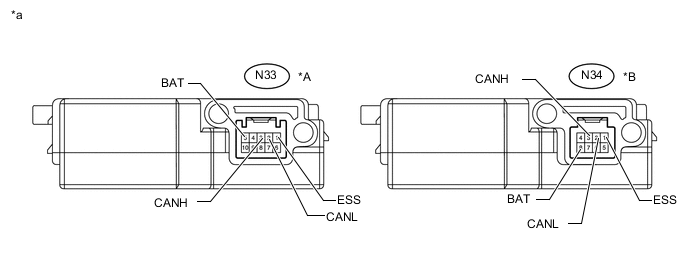
Text in Illustration *A w/ Variable Gear Ratio Steering System *B w/o Variable Gear Ratio Steering System *a Component without harness connected
(Steering Angle Sensor)
- -
-
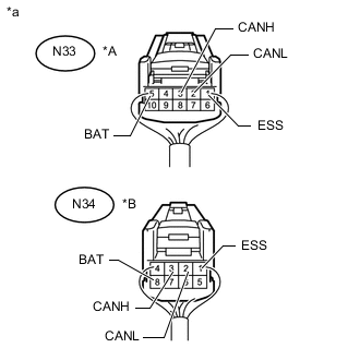
Text in Illustration *A w/ Variable Gear Ratio Steering System *B w/o Variable Gear Ratio Steering System *a Rear view of wire harness connector
(to Steering Angle Sensor)
Disconnect the steering angle sensor connector.
-
Measure the resistance according to the value(s) in the table below.
w/ Variable Gear Ratio Steering System Terminal No. (Symbol) Wiring Color Terminal Description Condition Specified Condition N33-3 (CANH) - N33-2 (CANL) R - W HIGH-level CAN bus line - LOW-level CAN bus line Cable disconnected from negative (-) auxiliary battery terminal 54 to 69 Ω N33-3 (CANH) - N33-1 (ESS) R - W-B HIGH-level CAN bus line - Ground Cable disconnected from negative (-) auxiliary battery terminal 200 Ω or higher N33-2 (CANL) - N33-1 (ESS) W - W-B LOW-level CAN bus line - Ground Cable disconnected from negative (-) auxiliary battery terminal 200 Ω or higher N33-3 (CANH) - N33-5 (BAT) R - P HIGH-level CAN bus line - auxiliary battery positive (+) Cable disconnected from negative (-) auxiliary battery terminal 6 kΩ or higher N33-2 (CANL) - N33-5 (BAT) W - P LOW-level CAN bus line - auxiliary battery positive (+) Cable disconnected from negative (-) auxiliary battery terminal 6 kΩ or higher w/o Variable Gear Ratio Steering System Terminal No. (Symbol) Wiring Color Terminal Description Condition Specified Condition N34-3 (CANH) - N34-2 (CANL) R - W HIGH-level CAN bus line - LOW-level CAN bus line Cable disconnected from negative (-) auxiliary battery terminal 54 to 69 Ω N34-3 (CANH) - N34-1 (ESS) R - W-B HIGH-level CAN bus line - Ground Cable disconnected from negative (-) auxiliary battery terminal 200 Ω or higher N34-2 (CANL) - N34-1 (ESS) W - W-B LOW-level CAN bus line - Ground Cable disconnected from negative (-) auxiliary battery terminal 200 Ω or higher N34-3 (CANH) - N34-8 (BAT) R - B HIGH-level CAN bus line - auxiliary battery positive (+) Cable disconnected from negative (-) auxiliary battery terminal 6 kΩ or higher N34-2 (CANL) - N34-8 (BAT) W - B LOW-level CAN bus line - auxiliary battery positive (+) Cable disconnected from negative (-) auxiliary battery terminal 6 kΩ or higher
-
-
CHECK YAW RATE SENSOR
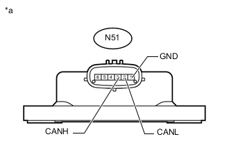
Text in Illustration *a Component without harness connected
(Yaw Rate Sensor)
-
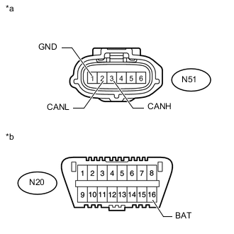
Text in Illustration *a Front view of wire harness connector
(to Yaw Rate Sensor)
*b Front view of DLC3 Disconnect the yaw rate sensor connector.
-
Measure the resistance according to the value(s) in the table below.
Terminal No. (Symbol) Wiring Color Terminal Description Condition Specified Condition N51-3 (CANH) - N51-2 (CANL) B - W HIGH-level CAN bus line - LOW-level CAN bus line Cable disconnected from negative (-) auxiliary battery terminal 54 to 69 Ω N51-3 (CANH) - N51-1 (GND) B - W-B HIGH-level CAN bus line - Ground Cable disconnected from negative (-) auxiliary battery terminal 200 Ω or higher N51-2 (CANL) - N51-1 (GND) W - W-B LOW-level CAN bus line - Ground Cable disconnected from negative (-) auxiliary battery terminal 200 Ω or higher N51-3 (CANH) - N20-16 (BAT) B - W HIGH-level CAN bus line - auxiliary battery positive (+) Cable disconnected from negative (-) auxiliary battery terminal 6 kΩ or higher N51-2 (CANL) - N20-16 (BAT) W - W LOW-level CAN bus line - auxiliary battery positive (+) Cable disconnected from negative (-) auxiliary battery terminal 6 kΩ or higher
-
-
CHECK FRONT STEERING CONTROL ECU (w/ Variable Gear Ratio Steering System)
-
Terminal Connector Click here.
-
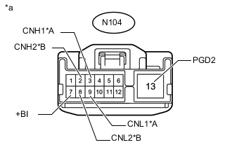
Text in Illustration *A Bus 2 *B Bus 4 *a Front view of wire harness connector
(to Front Steering Control ECU)
Disconnect the front steering control ECU connector.
-
Measure the resistance according to the value(s) in the table below.
Bus 2 Terminal No. (Symbol) Wiring Color Terminal Description Condition Specified Condition N104-3 (CNH1) - N104-9 (CNL1) R - W HIGH-level CAN bus line - LOW-level CAN bus line Cable disconnected from negative (-) auxiliary battery terminal 54 to 69 Ω N104-3 (CNH1) - N104-13 (PGD2) R - W-B HIGH-level CAN bus line - Ground Cable disconnected from negative (-) auxiliary battery terminal 200 Ω or higher N104-9 (CNL1) - N104-13 (PGD2) W - W-B LOW-level CAN bus line - Ground Cable disconnected from negative (-) auxiliary battery terminal 200 Ω or higher N104-3 (CNH1) - N104-7 (+BI) R - GR HIGH-level CAN bus line - auxiliary battery positive (+) Cable disconnected from negative (-) auxiliary battery terminal 6 kΩ or higher N104-9 (CNL1) - N104-7 (+BI) W - GR LOW-level CAN bus line - auxiliary battery positive (+) Cable disconnected from negative (-) auxiliary battery terminal 6 kΩ or higher Bus 4 Terminal No. (Symbol) Wiring Color Terminal Description Condition Specified Condition N104-2 (CNH2) - N104-8 (CNL2) G - SB HIGH-level CAN bus line - LOW-level CAN bus line Cable disconnected from negative (-) auxiliary battery terminal 54 to 69 Ω N104-2 (CNH2) - N104-13 (PGD2) G - W-B HIGH-level CAN bus line - Ground Cable disconnected from negative (-) auxiliary battery terminal 200 Ω or higher N104-8 (CNL2) - N104-13 (PGD2) SB - W-B LOW-level CAN bus line - Ground Cable disconnected from negative (-) auxiliary battery terminal 200 Ω or higher N104-2 (CNH2) - N104-7 (+BI) G - GR HIGH-level CAN bus line - auxiliary battery positive (+) Cable disconnected from negative (-) auxiliary battery terminal 6 kΩ or higher N104-8 (CNL2) - N104-7 (+BI) SB - GR LOW-level CAN bus line - auxiliary battery positive (+) Cable disconnected from negative (-) auxiliary battery terminal 6 kΩ or higher
-
-
CHECK REAR STEERING CONTROL ECU (w/ Rear Dynamic Steering System)
-
Terminal Connector Click here.
-
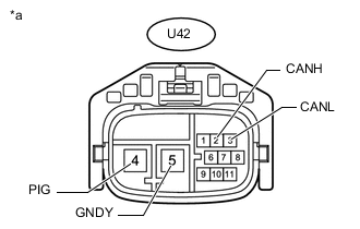
Text in Illustration *a Front view of wire harness connector
(to Rear Steering Control ECU)
Disconnect the rear steering control ECU connector.
-
Measure the resistance according to the value(s) in the table below.
Terminal No. (Symbol) Wiring Color Terminal Description Condition Specified Condition U42-2 (CANH) - U42-3 (CANL) G - SB HIGH-level CAN bus line - LOW-level CAN bus line Cable disconnected from negative (-) auxiliary battery terminal 54 to 69 Ω U42-2 (CANH) - U42-5 (GNDY) G - W-B HIGH-level CAN bus line - Ground Cable disconnected from negative (-) auxiliary battery terminal 200 Ω or higher U42-3 (CANL) - U42-5 (GNDY) SB - W-B LOW-level CAN bus line - Ground Cable disconnected from negative (-) auxiliary battery terminal 200 Ω or higher U42-2 (CANH) - U42-4 (PIG) G - B HIGH-level CAN bus line - auxiliary battery positive (+) Cable disconnected from negative (-) auxiliary battery terminal 6 kΩ or higher U42-3 (CANL) - U42-4 (PIG) SB - B LOW-level CAN bus line - auxiliary battery positive (+) Cable disconnected from negative (-) auxiliary battery terminal 6 kΩ or higher
-
-
CHECK FRONT MULTIPLEX NETWORK DOOR ECU LH
-
Terminal Connector Click here.
-
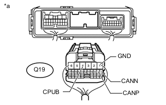
Text in Illustration *a Rear view of wire harness connector
(to Front Multiplex Network Door ECU LH)
Disconnect the front multiplex network door ECU LH connector.
-
Measure the resistance according to the value(s) in the table below.
Terminal No. (Symbol) Wiring Color Terminal Description Condition Specified Condition Q19-8 (CANP) - Q19-7 (CANN) R - G HIGH-level CAN bus line - LOW-level CAN bus line Cable disconnected from negative (-) auxiliary battery terminal 54 to 69 Ω Q19-8 (CANP) - Q19-1 (GND) R - W-B HIGH-level CAN bus line - Ground Cable disconnected from negative (-) auxiliary battery terminal 200 Ω or higher Q19-7 (CANN) - Q19-1 (GND) G - W-B LOW-level CAN bus line - Ground Cable disconnected from negative (-) auxiliary battery terminal 200 Ω or higher Q19-8 (CANP) - Q19-4 (CPUB) R - P HIGH-level CAN bus line - auxiliary battery positive (+) Cable disconnected from negative (-) auxiliary battery terminal 6 kΩ or higher Q19-7 (CANN) - Q19-4 (CPUB) G - P LOW-level CAN bus line - auxiliary battery positive (+) Cable disconnected from negative (-) auxiliary battery terminal 6 kΩ or higher
-
-
CHECK FRONT MULTIPLEX NETWORK DOOR ECU RH
-
Terminal Connector Click here.
-
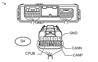
Text in Illustration *a Rear view of wire harness connector
(to Front Multiplex Network Door ECU RH)
Disconnect the front multiplex network door ECU RH connector.
-
Measure the resistance according to the value(s) in the table below.
Terminal No. (Symbol) Wiring Color Terminal Description Condition Specified Condition Q4-8 (CANP) - Q4-7 (CANN) R - G HIGH-level CAN bus line - LOW-level CAN bus line Cable disconnected from negative (-) auxiliary battery terminal 54 to 69 Ω Q4-8 (CANP) - Q4-1 (GND) R - W-B HIGH-level CAN bus line - Ground Cable disconnected from negative (-) auxiliary battery terminal 200 Ω or higher Q4-7 (CANN) - Q4-1 (GND) G - W-B LOW-level CAN bus line - Ground Cable disconnected from negative (-) auxiliary battery terminal 200 Ω or higher Q4-8 (CANP) - Q4-4 (CPUB) R - P HIGH-level CAN bus line - auxiliary battery positive (+) Cable disconnected from negative (-) auxiliary battery terminal 6 kΩ or higher Q4-7 (CANN) - Q4-4 (CPUB) G - P LOW-level CAN bus line - auxiliary battery positive (+) Cable disconnected from negative (-) auxiliary battery terminal 6 kΩ or higher
-
-
CHECK MULTIPLEX TILT AND TELESCOPIC ECU
-
Terminal Connector Click here.
-
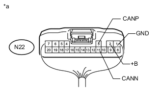
Text in Illustration *a Rear view of wire harness connector
(to Multiplex Tilt and Telescopic ECU)
Disconnect the multiplex tilt and telescopic ECU connector.
-
Measure the resistance according to the value(s) in the table below.
Terminal No. (Symbol) Wiring Color Terminal Description Condition Specified Condition N22-3 (CANP) - N22-11 (CANN) R - GR HIGH-level CAN bus line - LOW-level CAN bus line Cable disconnected from negative (-) auxiliary battery terminal 54 to 69 Ω N22-3 (CANP) - N22-1 (GND) R - W-B HIGH-level CAN bus line - Ground Cable disconnected from negative (-) auxiliary battery terminal 200 Ω or higher N22-11 (CANN) - N22-1 (GND) GR - W-B LOW-level CAN bus line - Ground Cable disconnected from negative (-) auxiliary battery terminal 200 Ω or higher N22-3 (CANP) - N22-2 (+B) R - L HIGH-level CAN bus line - auxiliary battery positive (+) Cable disconnected from negative (-) auxiliary battery terminal 6 kΩ or higher N22-11 (CANN) - N22-2 (+B) GR - L LOW-level CAN bus line - auxiliary battery positive (+) Cable disconnected from negative (-) auxiliary battery terminal 6 kΩ or higher
-
-
CHECK POSITION CONTROL ECU ASSEMBLY RH (except Standard Seat Type)
-
Terminal Connector Click here.
-
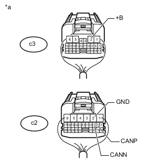
Text in Illustration *a Rear view of wire harness connector
(to Position Control ECU Assembly LH)
Disconnect the position control ECU assembly RH connectors.
-
Measure the resistance according to the value(s) in the table below.
Terminal No. (Symbol) Wiring Color Terminal Description Condition Specified Condition c2-8 (CANP) - c2-9 (CANN) W - R HIGH-level CAN bus line - LOW-level CAN bus line Cable disconnected from negative (-) auxiliary battery terminal 54 to 69 Ω c2-8 (CANP) - c2-2 (GND) W - B HIGH-level CAN bus line - Ground Cable disconnected from negative (-) auxiliary battery terminal 200 Ω or higher c2-9 (CANN) - c2-2 (GND) R - B LOW-level CAN bus line - Ground Cable disconnected from negative (-) auxiliary battery terminal 200 Ω or higher c2-8 (CANP) - c3-2 (+B) W - G HIGH-level CAN bus line - auxiliary battery positive (+) Cable disconnected from negative (-) auxiliary battery terminal 6 kΩ or higher c2-9 (CANN) - c3-2 (+B) R - G LOW-level CAN bus line - auxiliary battery positive (+) Cable disconnected from negative (-) auxiliary battery terminal 6 kΩ or higher
-
-
CHECK POWER SEAT SWITCH ASSEMBLY (for Standard Seat Type)
-
Terminal Connector Click here.
-
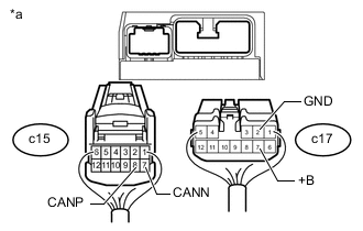
Text in Illustration *a Rear view of wire harness connector
(to Power Seat Switch Assembly)
Disconnect the power seat switch assembly connectors.
-
Measure the resistance according to the value(s) in the table below.
Terminal No. (Symbol) Wiring Color Terminal Description Condition Specified Condition c15-8 (CANP) - c15-7 (CANN) W - R HIGH-level CAN bus line - LOW-level CAN bus line Cable disconnected from negative (-) auxiliary battery terminal 54 to 69 Ω c15-8 (CANP) - c17-2 (GND) W - B HIGH-level CAN bus line - Ground Cable disconnected from negative (-) auxiliary battery terminal 200 Ω or higher c15-7 (CANN) - c17-2 (GND) R - B LOW-level CAN bus line - Ground Cable disconnected from negative (-) auxiliary battery terminal 200 Ω or higher c15-8 (CANP) - c17-7 (+B) W - G HIGH-level CAN bus line - auxiliary battery positive (+) Cable disconnected from negative (-) auxiliary battery terminal 6 kΩ or higher c15-7 (CANN) - c17-7 (+B) R - G LOW-level CAN bus line - auxiliary battery positive (+) Cable disconnected from negative (-) auxiliary battery terminal 6 kΩ or higher
-
-
CHECK POSITION CONTROL ECU ASSEMBLY LH (for Luxury Seat Type)
-
Terminal Connector Click here.
-
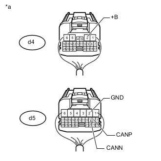
Text in Illustration *a Rear view of wire harness connector
(to Position Control ECU Assembly LH)
Disconnect the position control ECU assembly LH connectors.
-
Measure the resistance according to the value(s) in the table below.
Terminal No. (Symbol) Wiring Color Terminal Description Condition Specified Condition d5-8 (CANP) - d5-9 (CANN) R - G HIGH-level CAN bus line - LOW-level CAN bus line Cable disconnected from negative (-) auxiliary battery terminal 54 to 69 Ω d5-8 (CANP) - d5-2 (GND) R - B HIGH-level CAN bus line - Ground Cable disconnected from negative (-) auxiliary battery terminal 200 Ω or higher d5-9 (CANN) - d5-2 (GND) G - B LOW-level CAN bus line - Ground Cable disconnected from negative (-) auxiliary battery terminal 200 Ω or higher d5-8 (CANP) - d4-2 (+B) R - G HIGH-level CAN bus line - auxiliary battery positive (+) Cable disconnected from negative (-) auxiliary battery terminal 6 kΩ or higher d5-9 (CANN) - d4-2 (+B) G - G LOW-level CAN bus line - auxiliary battery positive (+) Cable disconnected from negative (-) auxiliary battery terminal 6 kΩ or higher
-
-
CHECK LUGGAGE CLOSER MOTOR ASSEMBLY (w/ Power Trunk Lid System)
-
Terminal Connector Click here.
-
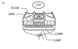
Text in Illustration *a Rear view of wire harness connector
(to Luggage Closer Motor Assembly)
Disconnect the luggage closer motor assembly connector.
-
Measure the resistance according to the value(s) in the table below.
Terminal No. (Symbol) Wiring Color Terminal Description Condition Specified Condition U33-6 (CANP) - U33-5 (CANN) G - GR HIGH-level CAN bus line - LOW-level CAN bus line Cable disconnected from negative (-) auxiliary battery terminal 54 to 69 Ω U33-6 (CANP) - U33-11 (GND) G - W-B HIGH-level CAN bus line - Ground Cable disconnected from negative (-) auxiliary battery terminal 200 Ω or higher U33-5 (CANN) - U33-11 (GND) GR - W-B LOW-level CAN bus line - Ground Cable disconnected from negative (-) auxiliary battery terminal 200 Ω or higher U33-6 (CANP) - U33-10 (ECUB) G - P HIGH-level CAN bus line - auxiliary battery positive (+) Cable disconnected from negative (-) auxiliary battery terminal 6 kΩ or higher U33-5 (CANN) - U33-10 (ECUB) GR - P LOW-level CAN bus line - auxiliary battery positive (+) Cable disconnected from negative (-) auxiliary battery terminal 6 kΩ or higher
-
-
CHECK MULTIPLEX NETWORK DOOR ECU (w/o Power Trunk Lid System)
-
Terminal Connector Click here.
-
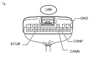
Text in Illustration *a Rear view of wire harness connector
(to Multiplex Network Door ECU)
Disconnect the multiplex network door ECU connector.
-
Measure the resistance according to the value(s) in the table below.
Terminal No. (Symbol) Wiring Color Terminal Description Condition Specified Condition U68-10 (CANP) - U68-11 (CANN) G - GR HIGH-level CAN bus line - LOW-level CAN bus line Cable disconnected from negative (-) auxiliary battery terminal 54 to 69 Ω U68-10 (CANP) - U68-1 (GND) G - W-B HIGH-level CAN bus line - Ground Cable disconnected from negative (-) auxiliary battery terminal 200 Ω or higher U68-11 (CANN) - U68-1 (GND) GR - W-B LOW-level CAN bus line - Ground Cable disconnected from negative (-) auxiliary battery terminal 200 Ω or higher U68-10 (CANP) - U68-18 (ECUB) G - P HIGH-level CAN bus line - auxiliary battery positive (+) Cable disconnected from negative (-) auxiliary battery terminal 6 kΩ or higher U68-11 (CANN) - U68-18 (ECUB) GR - P LOW-level CAN bus line - auxiliary battery positive (+) Cable disconnected from negative (-) auxiliary battery terminal 6 kΩ or higher
-
-
CHECK ABSORBER CONTROL ECU (w/ Adaptive Variable Suspension System)
-
Terminal Connector Click here.
-
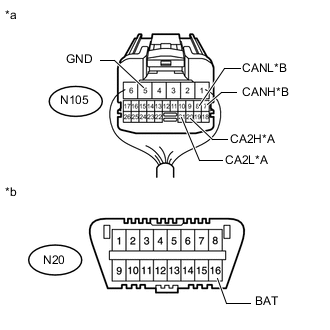
Text in Illustration *A Bus 4 *B Bus 5 *a Rear view of wire harness connector
(to Absorber Control ECU)
*b Front view of DLC3 Disconnect the absorber control ECU connector.
-
Measure the resistance according to the value(s) in the table below.
Bus 4 Terminal No. (Symbol) Wiring Color Terminal Description Condition Specified Condition N105-20 (CA2H) - N105-21 (CA2L) L - SB HIGH-level CAN bus line - LOW-level CAN bus line Cable disconnected from negative (-) auxiliary battery terminal 54 to 69 Ω N105-20 (CA2H) - N105-5 (GND) L - W-B HIGH-level CAN bus line - Ground Cable disconnected from negative (-) auxiliary battery terminal 200 Ω or higher N105-21 (CA2L) - N105-5 (GND) SB - W-B LOW-level CAN bus line - Ground Cable disconnected from negative (-) auxiliary battery terminal 200 Ω or higher N105-20 (CA2H) - N20-16 (BAT) L - W HIGH-level CAN bus line - auxiliary battery positive (+) Cable disconnected from negative (-) auxiliary battery terminal 6 kΩ or higher N105-21 (CA2L) - N20-16 (BAT) SB - W LOW-level CAN bus line - auxiliary battery positive (+) Cable disconnected from negative (-) auxiliary battery terminal 6 kΩ or higher Bus 5 Terminal No. (Symbol) Wiring Color Terminal Description Condition Specified Condition N105-7 (CANH) - N105-8 (CANL) V - LG HIGH-level CAN bus line - LOW-level CAN bus line Cable disconnected from negative (-) auxiliary battery terminal 54 to 69 Ω N105-7 (CANH) - N105-5 (GND) V - W-B HIGH-level CAN bus line - Ground Cable disconnected from negative (-) auxiliary battery terminal 200 Ω or higher N105-8 (CANL) - N105-5 (GND) LG - W-B LOW-level CAN bus line - Ground Cable disconnected from negative (-) auxiliary battery terminal 200 Ω or higher N105-7 (CANH) - N20-16 (BAT) V - W HIGH-level CAN bus line - auxiliary battery positive (+) Cable disconnected from negative (-) auxiliary battery terminal 6 kΩ or higher N105-8 (CANL) - N20-16 (BAT) LG - W LOW-level CAN bus line - auxiliary battery positive (+) Cable disconnected from negative (-) auxiliary battery terminal 6 kΩ or higher
-
-
CHECK CLEARANCE WARNING ECU ASSEMBLY (w/ LEXUS Parking Assist-sensor System)
-
Terminal Connector Click here.
-
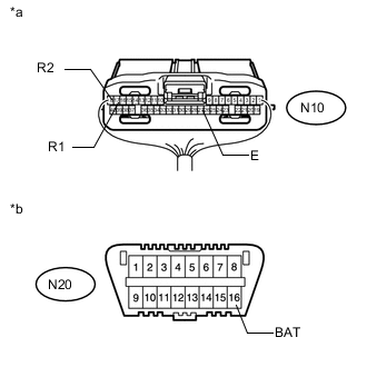
Text in Illustration *a Rear view of wire harness connector
(to Clearance Warning ECU Assembly)
*b Front view of DLC3 Disconnect the clearance warning ECU assembly connector.
-
Measure the resistance according to the value(s) in the table below.
Terminal No. (Symbol) Wiring Color Terminal Description Condition Specified Condition N10-17 (R1) - N10-18 (R2) L - LG HIGH-level CAN bus line - LOW-level CAN bus line Cable disconnected from negative (-) auxiliary battery terminal 54 to 69 Ω N10-17 (R1) - N10-27 (E) L - W-B HIGH-level CAN bus line - Ground Cable disconnected from negative (-) auxiliary battery terminal 200 Ω or higher N10-18 (R2) - N10-27 (E) LG - W-B LOW-level CAN bus line - Ground Cable disconnected from negative (-) auxiliary battery terminal 200 Ω or higher N10-17 (R1) - N20-16 (BAT) L - W HIGH-level CAN bus line - auxiliary battery positive (+) Cable disconnected from negative (-) auxiliary battery terminal 6 kΩ or higher N10-18 (R2) - N20-16 (BAT) LG - W LOW-level CAN bus line - auxiliary battery positive (+) Cable disconnected from negative (-) auxiliary battery terminal 6 kΩ or higher
-
-
CHECK BLIND SPOT MONITOR SENSOR RH (w/ Blind Spot Monitor System)
-
Terminal Connector Click here.
-
Disconnect the blind spot monitor sensor RH connector.
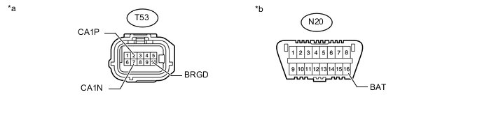
Text in Illustration *a Front view of wire harness connector
(to Blind Spot Monitor Sensor RH)
*b Front view of DLC3 -
Measure the resistance according to the value(s) in the table below.
Terminal No. (Symbol) Wiring Color Terminal Description Condition Specified Condition T53-2 (CA1P) - T53-7 (CA1N) L - LG HIGH-level CAN bus line - LOW-level CAN bus line Cable disconnected from negative (-) auxiliary battery terminal 54 to 69 Ω T53-2 (CA1P) - T53-10 (BRGD) L - W-B HIGH-level CAN bus line - Ground Cable disconnected from negative (-) auxiliary battery terminal 200 Ω or higher T53-7 (CA1N) - T53-10 (BRGD) LG - W-B LOW-level CAN bus line - Ground Cable disconnected from negative (-) auxiliary battery terminal 200 Ω or higher T53-2 (CA1P) - N20-16 (BAT) L - W HIGH-level CAN bus line - auxiliary battery positive (+) Cable disconnected from negative (-) auxiliary battery terminal 6 kΩ or higher T53-7 (CA1N) - N20-16 (BAT) LG - W LOW-level CAN bus line - auxiliary battery positive (+) Cable disconnected from negative (-) auxiliary battery terminal 6 kΩ or higher
-
-
CHECK MILLIMETER WAVE RADAR SENSOR ASSEMBLY (w/ Pre-crash Safety System)
-
Terminal Connector Click here.
-
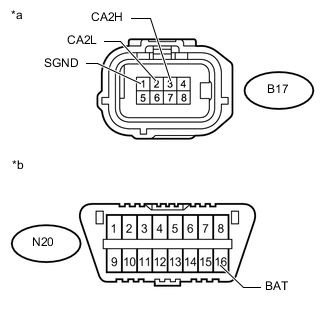
Text in Illustration *a Front view of wire harness connector
(to Millimeter Wave Radar Sensor Assembly)
*b Front view of DLC3 Disconnect the millimeter wave radar sensor assembly connector.
-
Measure the resistance according to the value(s) in the table below.
Terminal No. (Symbol) Wiring Color Terminal Description Switch Condition Specified Condition B17-3 (CA2H) - B17-2 (CA2L) B - L HIGH-level CAN bus line - LOW-level CAN bus line Cable disconnected from negative (-) auxiliary battery terminal 54 to 69 Ω B17-3 (CA2H) - B17-1 (SGND) B - BR HIGH-level CAN bus line - Ground Cable disconnected from negative (-) auxiliary battery terminal 200 Ω or higher B17-2 (CA2L) - B17-1 (SGND) L - BR LOW-level CAN bus line - Ground Cable disconnected from negative (-) auxiliary battery terminal 200 Ω or higher B17-3 (CA2H) - N20-16 (BAT) B - W HIGH-level CAN bus line - auxiliary battery positive (+) Cable disconnected from negative (-) auxiliary battery terminal 6 kΩ or higher B17-2 (CA2L) - N20-16 (BAT) L - W LOW-level CAN bus line - auxiliary battery positive (+) Cable disconnected from negative (-) auxiliary battery terminal 6 kΩ or higher
-
-
CHECK FORWARD RECOGNITION CAMERA (w/ Pre-crash Safety System)
-
Terminal Connector Click here.
-
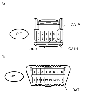
Text in Illustration *a Front view of wire harness connector
(to Forward Recognition Camera)
*b Front view of DLC3 Disconnect the forward recognition camera connector.
-
Measure the resistance according to the value(s) in the table below.
Terminal No. (Symbol) Wiring Color Terminal Description Switch Condition Specified Condition Y17-5 (CA1P) - Y17-11 (CA1N) L - LG HIGH-level CAN bus line - LOW-level CAN bus line Cable disconnected from negative (-) auxiliary battery terminal 54 to 69 Ω Y17-5 (CA1P) - Y17-10 (GND) L - W-B HIGH-level CAN bus line - Ground Cable disconnected from negative (-) auxiliary battery terminal 200 Ω or higher Y17-11 (CA1N) - Y17-10 (GND) LG - W-B LOW-level CAN bus line - Ground Cable disconnected from negative (-) auxiliary battery terminal 200 Ω or higher Y17-5 (CA1P) - N20-16 (BAT) L - W HIGH-level CAN bus line - auxiliary battery positive (+) Cable disconnected from negative (-) auxiliary battery terminal 6 kΩ or higher Y17-11 (CA1N) - N20-16 (BAT) LG - W LOW-level CAN bus line - auxiliary battery positive (+) Cable disconnected from negative (-) auxiliary battery terminal 6 kΩ or higher
-
-
CHECK HEADLIGHT ECU SUB-ASSEMBLY LH
-
Terminal Connector Click here.
-
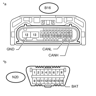
Text in Illustration *a Front view of wire harness connector
(to Headlight ECU Sub-assembly LH)
*b Front view of DLC3 Disconnect the headlight ECU sub-assembly LH connector.
-
Measure the resistance according to the value(s) in the table below.
Terminal No. (Symbol) Wiring Color Terminal Description Switch Condition Specified Condition B16-24 (CANH) - B16-23 (CANL) G - L HIGH-level CAN bus line - LOW-level CAN bus line Cable disconnected from negative (-) auxiliary battery terminal 54 to 69 Ω B16-24 (CANH) - B16-12 (GND) G - W-B HIGH-level CAN bus line - Ground Cable disconnected from negative (-) auxiliary battery terminal 200 Ω or higher B16-23 (CANL) - B16-12 (GND) L - W-B LOW-level CAN bus line - Ground Cable disconnected from negative (-) auxiliary battery terminal 200 Ω or higher B16-24 (CANH) - N20-16 (BAT) G - W HIGH-level CAN bus line - auxiliary battery positive (+) Cable disconnected from negative (-) auxiliary battery terminal 6 kΩ or higher B16-23 (CANL) - N20-16 (BAT) L - W LOW-level CAN bus line - auxiliary battery positive (+) Cable disconnected from negative (-) auxiliary battery terminal 6 kΩ or higher
-
-
CHECK COMBINATION METER MIRROR ECU (w/ Headup Display System)
-
Terminal Connector Click here.
-
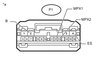
Text in Illustration *a Front view of wire harness connector
(to Combination Meter Mirror ECU)
Disconnect the combination meter mirror ECU connector.
-
Measure the resistance according to the value(s) in the table below.
Terminal No. (Symbol) Wiring Color Terminal Description Switch Condition Specified Condition P1-12 (MPX1) - P1-13 (MPX2) P - R HIGH-level CAN bus line - LOW-level CAN bus line Cable disconnected from negative (-) auxiliary battery terminal 54 to 69 Ω P1-12 (MPX1) - P1-4 (ES) P - W-B HIGH-level CAN bus line - Ground Cable disconnected from negative (-) auxiliary battery terminal 200 Ω or higher P1-13 (MPX2) - P1-4 (ES) R - W-B LOW-level CAN bus line - Ground Cable disconnected from negative (-) auxiliary battery terminal 200 Ω or higher P1-12 (MPX1) - P1-2 (B) P - L HIGH-level CAN bus line - auxiliary battery positive (+) Cable disconnected from negative (-) auxiliary battery terminal 6 kΩ or higher P1-13 (MPX2) - P1-2 (B) R - L LOW-level CAN bus line - auxiliary battery positive (+) Cable disconnected from negative (-) auxiliary battery terminal 6 kΩ or higher
-
-
CHECK DRIVING SUPPORT ECU ASSEMBLY (w/ Pre-crash Safety System)
-
Terminal Connector Click here.
-
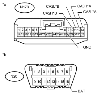
Text in Illustration *A Bus 4 *B Bus 5 *a Front view of wire harness connector
(to Driving Support ECU Assembly)
*b Front view of DLC3 Disconnect the driving support ECU assembly connector.
-
Measure the resistance according to the value(s) in the table below.
Bus 4 Terminal No. (Symbol) Wiring Color Terminal Description Switch Condition Specified Condition N173-12 (CA3H) - N173-13 (CA3L) G - SB HIGH-level CAN bus line - LOW-level CAN bus line Cable disconnected from negative (-) auxiliary battery terminal 54 to 69 Ω N173-12 (CA3H) - N173-28 (GND) G - W-B HIGH-level CAN bus line - Ground Cable disconnected from negative (-) auxiliary battery terminal 200 Ω or higher N173-13 (CA3L) - N173-28 (GND) SB - W-B LOW-level CAN bus line - Ground Cable disconnected from negative (-) auxiliary battery terminal 200 Ω or higher N173-12 (CA3H) - N20-16 (BAT) G - W HIGH-level CAN bus line - auxiliary battery positive (+) Cable disconnected from negative (-) auxiliary battery terminal 6 kΩ or higher N173-13 (CA3L) - N20-16 (BAT) SB - W LOW-level CAN bus line - auxiliary battery positive (+) Cable disconnected from negative (-) auxiliary battery terminal 6 kΩ or higher Bus 5 Terminal No. (Symbol) Wiring Color Terminal Description Switch Condition Specified Condition N173-10 (CA2H) - N173-11 (CA2L) V - LG HIGH-level CAN bus line - LOW-level CAN bus line Cable disconnected from negative (-) auxiliary battery terminal 54 to 69 Ω N173-10 (CA2H) - N173-28 (GND) V - W-B HIGH-level CAN bus line - Ground Cable disconnected from negative (-) auxiliary battery terminal 200 Ω or higher N173-11 (CA2L) - N173-28 (GND) LG - W-B LOW-level CAN bus line - Ground Cable disconnected from negative (-) auxiliary battery terminal 200 Ω or higher N173-10 (CA2H) - N20-16 (BAT) V - W HIGH-level CAN bus line - auxiliary battery positive (+) Cable disconnected from negative (-) auxiliary battery terminal 6 kΩ or higher N173-11 (CA2L) - N20-16 (BAT) LG - W LOW-level CAN bus line - auxiliary battery positive (+) Cable disconnected from negative (-) auxiliary battery terminal 6 kΩ or higher
-