LIN COMMUNICATION SYSTEM TERMINALS OF ECU
-
CHECK COWL SIDE JUNCTION BLOCK LH, MAIN BODY ECU (MULTIPLEX NETWORK BODY ECU)
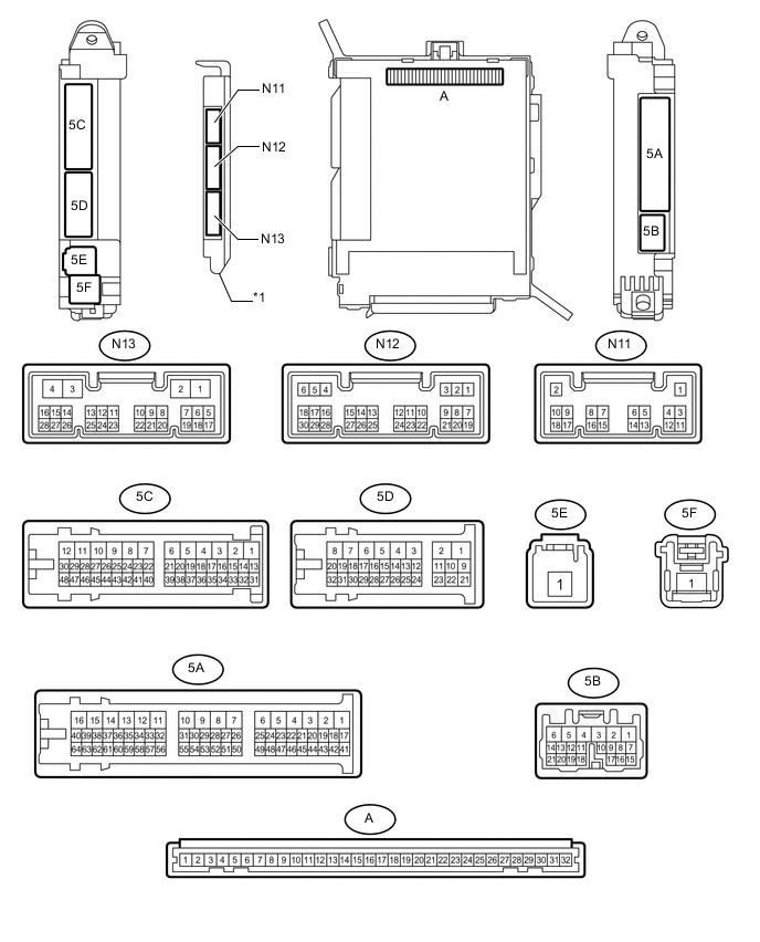
Text in Illustration *1 Main body ECU (Multiplex Network Body ECU) - -
-
Remove the main body ECU (multiplex network body ECU) from the cowl side junction block LH Click here.
-
Reconnect the cowl side junction block LH connectors.
-
Measure the resistance and voltage according to the value(s) in the table below.
Terminal No. (Symbol) Wiring Color Terminal Description Condition Specified Condition A-32 (IG) - Body ground - IG power supply Power switch on (IG) 11 to 14 V A-30 (BECU) - Body ground - Battery power supply Always 11 to 14 V A-29 (ACC) - Body ground - ACC power supply Power switch on (ACC) 11 to 14 V A-11 (GND1) - Body ground - Ground Always Below 1 Ω If the result is not as specified, there may be a malfunction on the wire harness side.
-
-
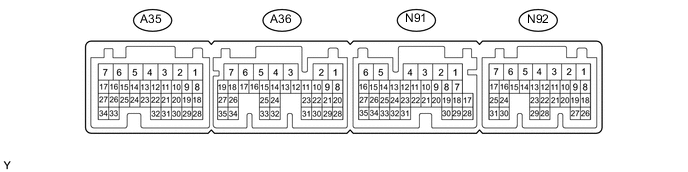
CHECK POWER MANAGEMENT CONTROL ECU
-
Disconnect the N91 and N92 Certification ECU connectors.
-
Measure the resistance and voltage according to the value(s) in the table below.
Terminal No. (Symbol) Wiring Color Terminal Description Condition Specified Condition N91-1 (AM22) - N91-6 (E) P - W-B Battery power supply Power switch on (IG) Below 1 Ω N92-7 (AM21) - N91-6 (E1) P - W-B IG power supply Power switch on (IG) 11 to 14 V N91-6 (E1) - Body ground W-B - Body ground Ground Always 11 to 14 V If the result is not as specified, there may be a malfunction on the wire harness side.
-
-
CHECK FRONT MULTIPLEX NETWORK DOOR ECU LH

-
Disconnect the Q19 front multiplex network door ECU LH connector.
-
Measure the resistance and voltage according to the value(s) in the table below.
Terminal No. (Symbol) Wiring Color Terminal Description Condition Specified Condition Q19-3 (SIG) - Body ground B - Body ground IG power supply Power switch on (IG) 11 to 14 V Q19-4 (CPUB) - Body ground P - Body ground Battery power supply Always 11 to 14 V Q19-6 (BDR) - Body ground V - Body ground Battery power supply Always 11 to 14 V Q19-16 (BCUT) - Body ground* W - Body ground Battery power supply Always 11 to 14 V Q19-1 (GND) - Body ground W-B - Body ground Ground Always Below 1 Ω
-
*: for LHD
If the result is not as specified, there may be a malfunction on the wire harness side.
-
-
-
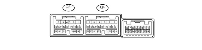
CHECK FRONT MULTIPLEX NETWORK DOOR ECU RH
-
Disconnect the Q4 front multiplex network door ECU RH connector.
-
Measure the resistance and voltage according to the value(s) in the table below.
Terminal No. (Symbol) Wiring Color Terminal Description Condition Specified Condition Q4-3 (SIG) - Body ground B - Body ground IG power supply Power switch on (IG) 11 to 14 V Q4-4 (CPUB) - Body ground P - Body ground Battery power supply Always 11 to 14 V Q4-6 (BDR) - Body ground V - Body ground Battery power supply Always 11 to 14 V Q4-16 (BCUT) - Body ground* L - Body ground Battery power supply Always 11 to 14 V Q4-1 (GND) - Body ground W-B - Body ground Ground Always Below 1 Ω
-
*: for RHD
If the result is not as specified, there may be a malfunction on the wire harness side.
-
-
-
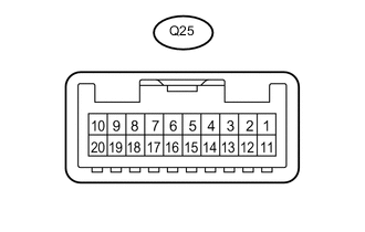
CHECK MULTIPLEX NETWORK MASTER SWITCH ASSEMBLY (for LHD)
-
Disconnect the Q25 multiplex network master switch assembly connector.
-
Measure the resistance and voltage according to the value(s) in the table below.
Terminal No. (Symbol) Wiring Color Terminal Description Condition Specified Condition Q25-12 (GND) - Body ground W-B - Body ground Ground Always Below 1 Ω Q25-11 (B) - Q25-12 (GND) P - W-B IG power supply Power switch off → Power switch on (IG) Below 1 V → 11 to 14 V If the result is not as specified, there may be a malfunction on the wire harness side.
-
-
CHECK MULTIPLEX NETWORK MASTER SWITCH ASSEMBLY (for RHD)
-
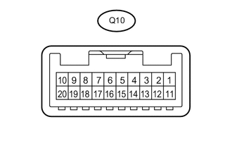
Disconnect the Q10 multiplex network master switch assembly connector.
-
Measure the resistance and voltage according to the value(s) in the table below.
Terminal No. (Symbol) Wiring Color Terminal Description Condition Specified Condition Q10-12 (GND) - Body ground W-B - Body ground Ground Always Below 1 Ω Q10-11 (B) - Q10-12 (GND) P - W-B IG power supply Power switch off → Power switch on (IG) Below 1 V → 11 to 14 V If the result is not as specified, there may be a malfunction on the wire harness side.
-
-
CHECK FRONT POWER WINDOW REGULATOR MOTOR ASSEMBLY LH

-
Disconnect the Q17 front power window regulator motor assembly LH connector.
-
Measure the resistance and voltage according to the value(s) in the table below.
Terminal No. (Symbol) Wiring Color Terminal Description Condition Specified Condition Q17-1 (E) - Body ground BR - Body ground Ground Always Below 1 Ω Q17-2 (B) - Q17-1 (E) R - BR Battery power supply Always 11 to 14 V If the result is not as specified, there may be a malfunction on the wire harness side.
-
-
CHECK FRONT POWER WINDOW REGULATOR MOTOR ASSEMBLY RH
-
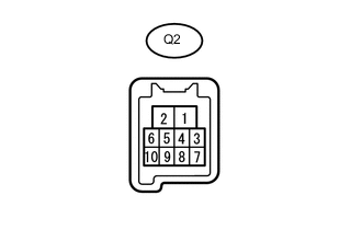
Disconnect the Q2 front power window regulator motor assembly RH connector.
-
Measure the resistance and voltage according to the value(s) in the table below.
Terminal No. (Symbol) Wiring Color Terminal Description Condition Specified Condition Q2-1 (E) - Body ground BR - Body ground Ground Always Below 1 Ω Q2-2 (B) - Q2-1 (E) R - BR Battery power supply Always 11 to 14 V If the result is not as specified, there may be a malfunction on the wire harness side.
-
-
CHECK REAR POWER WINDOW REGULATOR MOTOR ASSEMBLY LH
-
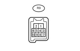
Disconnect the R9 rear power window regulator motor assembly LH connector.
-
Measure the resistance and voltage according to the value(s) in the table below.
Terminal No. (Symbol) Wiring Color Terminal Description Condition Specified Condition R9-1 (E) - Body ground W-B - Body ground Ground Always Below 1 Ω R9-2 (B) - R9-1 (E) R - W-B Battery power supply Always 11 to 14 V If the result is not as specified, there may be a malfunction on the wire harness side.
-
-
CHECK REAR POWER WINDOW REGULATOR MOTOR ASSEMBLY RH

-
Disconnect the R1 rear power window regulator motor assembly RH connector.
-
Measure the resistance and voltage according to the value(s) in the table below.
Terminal No. (Symbol) Wiring Color Terminal Description Condition Specified Condition R1-1 (E) - Body ground W-B - Body ground Ground Always Below 1 Ω R1-2 (B) - R1-1 (E) R - W-B Battery power supply Always 11 to 14 V If the result is not as specified, there may be a malfunction on the wire harness side.
-
-
CHECK SLIDING ROOF DRIVE GEAR SUB-ASSEMBLY (w/ Sliding Roof System)
-
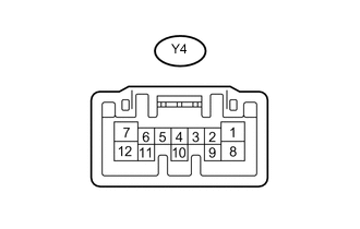
Disconnect the Y4 sliding roof drive gear sub-assembly connector.
-
Measure the resistance and voltage according to the value(s) in the table below.
Terminal No. (Symbols) Wiring Color Terminal Description Condition Specified Condition Y4-12 (E) - Body ground W-B - Body ground Ground Always Below 1 Ω Y4-8 (B) - Y4-12 (E) L - W-B Battery power supply Always 11 to 14 V If the result is not as specified, there may be a malfunction on the wire harness side.
-
-
CHECK CERTIFICATION ECU (SMART KEY ECU ASSEMBLY)
-
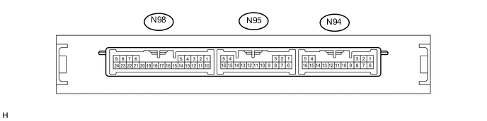
Disconnect the N94 and N95 Certification ECU connectors.
-
Measure the resistance and voltage according to the value(s) in the table below.
Terminal No. (Symbol) Wiring Color Terminal Description Condition Specified Condition N94-1 (E) - Body ground W-B - Body ground Ground Always Below 1 Ω N95-5 (+B) - N94-1 (E) GR - W-B Battery power supply Always 11 to 14 V N95-16 (IG) - N94-1 (E) B - W-B IG power supply Power switch off → Power switch on (IG) Below 1 V → 11 to 14 V If the result is not as specified, there may be a malfunction on the wire harness side.
-
-
CHECK ID CODE BOX (IMMOBILISER CODE ECU)
-
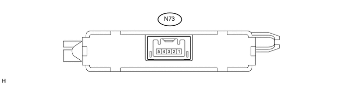
Disconnect the N73 ID code box connector.
-
Measure the resistance and voltage according to the value(s) in the table below.
Terminal No. (Symbol) Wiring Color Terminal Description Condition Specified Condition N73-5 (GND) - Body ground W-B - Body ground Ground Always Below 1 Ω N73-1 (+B) - N73-5 (GND) GR - W-B Battery power supply Always 11 to 14 V If the result is not as specified, there may be a malfunction on the wire harness side.
-
-
CHECK STEERING LOCK ACTUATOR ASSEMBLY
-
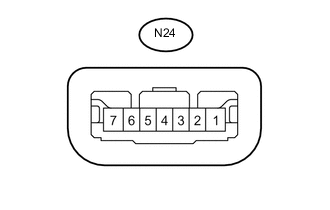
Disconnect the N24 steering lock actuator assembly connector.
-
Measure the resistance and voltage according to the value(s) in the table below.
Terminal No. (Symbol) Wiring Color Terminal Description Condition Specified Condition N24-1 (GND) - Body ground W-B - Body ground Ground Always Below 1 Ω N24-7 (B) - N24-1 (GND) L - W-B Battery power supply Always 11 to 14 V If the result is not as specified, there may be a malfunction on the wire harness side.
-
-
CHECK RAIN SENSOR (w/ Rain Sensor)
-
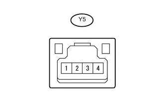
Disconnect the Y5 rain sensor connector.
-
Measure the resistance and voltage according to the value(s) in the table below.
Terminal No. (Symbol) Wiring Color Terminal Description Condition Specified Condition Y5-2 (ES) - Body ground W - Body ground Ground Always Below 1 Ω Y5-4 (SIG) - Y5-2 (ES) P - W IG power supply Power switch off → Power switch on (IG) Below 1 V → 11 to 14 V If the result is not as specified, there may be a malfunction on the wire harness side.
-
-
CHECK REFRESHING SEAT SWITCH (w/ Refreshing Seat Switch)
-
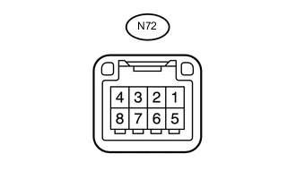
Disconnect the N72 refreshing seat switch connector.
-
Measure the resistance and voltage according to the value(s) in the table below.
Terminal No. (Symbol) Wiring Color Terminal Description Condition Specified Condition N72-4 (E) - Body ground W-B - Body ground Ground Always Below 1 Ω N72-1 (IG) - N72-4 (E) LG - W-B IG power supply Power switch off → Power switch on (IG) Below 1 V → 11 to 14 V If the result is not as specified, there may be a malfunction on the wire harness side.
-
-
CHECK REAR CONTROL SWITCH (w/ Rear Control Switch)
-
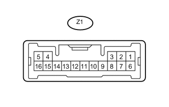
Disconnect the Z1 rear control switch connector.
-
Measure the resistance and voltage according to the value(s) in the table below.
Terminal No. (Symbol) Wiring Color Terminal Description Condition Specified Condition Z1-7 (IG+) - Z1-5 (E) L - W-B IG power supply Power switch off → Power switch on (IG) Below 1 V → 11 to 14 V Z1-5 (E) - Body ground W-B - Body ground Ground Always Below 1 Ω If the result is not as specified, there may be a malfunction on the wire harness side.
-
-
CHECK AIR CONDITIONING AMPLIFIER ASSEMBLY
-
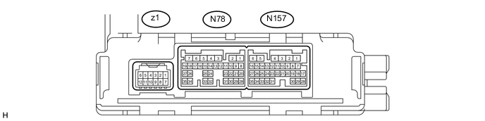
Disconnect the N78 air conditioning amplifier assembly connector.
-
Measure the resistance and voltage according to the value(s) in the table below.
Terminal No. (Symbols) Wiring Color Terminal Description Condition Specified Condition N78-5 (IG+) - N78-1 (GND) L - W-B IG power supply Power switch off → Power switch on (IG) Below 1 V → 11 to 14 V N78-6 (+B1) - N78-1 (GND) W - W-B Battery power supply Always 11 to 14 V N78-1 (GND) - Body ground W-B - Body ground Ground Always Below 1 Ω If the result is not as specified, there may be a malfunction on the wire harness side.
-
-
CHECK WINDSHIELD WIPER SWITCH ASSEMBLY
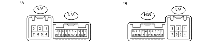
Text in Illustration *A for LH Side *B for RH Side
-
Disconnect the N35 windshield wiper switch assembly connector.
-
Measure the resistance and voltage according to the value(s) in the table below.
Terminal No. (Symbol) Wiring Color Terminal Description Condition Specified Condition N35-7 (E) - Body ground W-B - Body ground Ground Always Below 1 Ω N35-2 (+B) - N35-7 (E) SB - W-B IG power supply Power switch off → Power switch on (IG) Below 1 V → 11 to 14 V If the result is not as specified, there may be a malfunction on the wire harness side.
-