ELECTRONICALLY CONTROLLED BRAKE SYSTEM, Diagnostic DTC:C1241, C1242

| DTC Code | DTC Name |
|---|---|
| C1241 | Low or High Power Supply Voltage |
| C1242 | Open Circuit in IG1/IG2 Power Source Circuit |
DESCRIPTION
If a malfunction is detected in the power supply circuit, the skid control ECU assembly power source voltage drops, or there is insufficient voltage to operate either ABS main relay 1 or ABS main relay 2, the skid control ECU assembly will store these codes.
These codes may be also be stored if the auxiliary battery voltage drops below 9.5 V.
Tech Tips
DTC C1256 (Accumulator Low Pressure) may also be memorized if there is a drop in power source voltage.
| DTC Code | INF Code | DTC Detection Condition | Trouble Area |
|---|---|---|---|
| C1241 | 81 | System main relay 1 is under the following conditions when the power switch is on (READY):
|
|
| ↑ | 82 | System main relay 2 is under the following conditions when the power switch is on (READY):
|
↑ |
| ↑ | 83 | With the power switch on (READY), the capacitor mode signal is received from the brake control power supply assembly while the vehicle is driven at low speed for 7 seconds or more, or the vehicle is driven at medium to high speed for 3 seconds or more. |
|
| ↑ | 91 92 |
Either of the following is detected:
|
|
| ↑ | 93 94 |
Either of the following is detected:
|
↑ |
| C1242 | 87 | The power supply voltage is not applied to the IG1 terminal, power supply voltage is applied to the IG2 terminal, and +BI1 terminal voltage is 9.5 V or more for 4 seconds or more. |
|
| ↑ | 88 | With the vehicle wheel speed at 10 km/h or more and the communication with the power management control ECU functioning normally, power supply voltage is applied to the IG1 terminal, power supply voltage is not applied to the IG2 terminal, and +BI1 terminal voltage is 9.5 V or more for 4 seconds or more. |
|
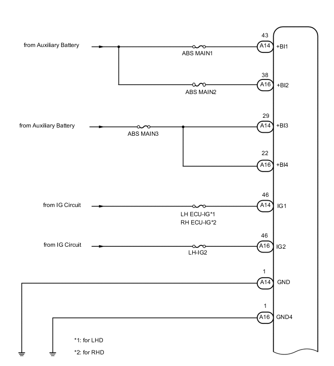
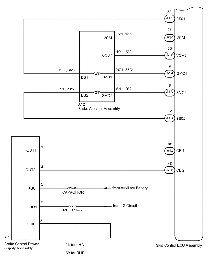
WIRING DIAGRAM
CAUTION / NOTICE / HINT
Note
-
When replacing the skid control ECU assembly, perform initialization and calibration of the linear solenoid valve Click here.
-
Inspect the fuses for circuits related to this system before performing the following inspection procedure.
PROCEDURE
-
CHECK HYBRID CONTROL SYSTEM
-
Check if the hybrid control system DTC is output (for 2GR-FXE: See page , for 2AR-FSE: Click here.
Result Result Proceed to DTC is not output A DTC is output (for 2GR-FXE) B DTC is output (for 2AR-FSE) C
B 
INSPECT HYBRID CONTROL SYSTEM Click here
C
INSPECT HYBRID CONTROL SYSTEM Click here
A 
-
-
CHECK DTC
-
Check that no main relay, stroke sensor and/or brake control power supply assembly DTCs are output Click here.
Result Result Proceed to Main relay, stroke sensor and brake control power supply assembly DTC is not output A Main relay, stroke sensor and/or brake control power supply assembly DTC is output B
B
REPAIR CIRCUITS INDICATED BY OUTPUT DTCS Click here
A
-
-
CHECK AUXILIARY BATTERY
-
Check the auxiliary battery voltage.
Standard Voltage Tester Connection Switch Condition Specified Condition Auxiliary battery Power switch on (IG) 11 to 14 V Auxiliary battery Power switch on (READY) 11 to 15.5 V
NG
CHARGE OR REPLACE AUXILIARY BATTERY
OK
-
-
CHECK HARNESS AND CONNECTOR (POWER SOURCE TERMINAL)
-
Make sure that there is no looseness at the locking part and the connecting part of the connectors.
-
Disconnect the skid control ECU assembly connectors.
-
Measure the voltage according to the value(s) in the table below.
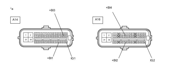
Standard Voltage Tester Connection Condition Specified Condition A14-43 (+BI1) - Body ground Always 11 to 14 V A16-38 (+BI2) - Body ground Always 11 to 14 V A14-29 (+BI3) - Body ground Always 11 to 14 V A16-22 (+BI4) - Body ground Always 11 to 14 V A14-46 (IG1) - Body ground Power switch on (IG) 11 to 14 V A16-46 (IG2) - Body ground Power switch on (IG) 11 to 14 V Text in Illustration *a Front view of wire harness connector
(to Skid Control ECU Assembly)
NG
REPAIR OR REPLACE HARNESS OR CONNECTOR (POWER SOURCE CIRCUIT)
OK
-
-
CHECK HARNESS AND CONNECTOR (GND TERMINAL)
-
Turn the power switch off.
-
Measure the resistance according to the value(s) in the table below.
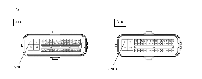
Standard Resistance Tester Connection Condition Specified Condition A14-1 (GND) - Body ground Always Below 1 Ω A16-1 (GND4) - Body ground Always Below 1 Ω Text in Illustration *a Front view of wire harness connector
(to Skid Control ECU Assembly)
NG
REPAIR OR REPLACE HARNESS OR CONNECTOR (GND CIRCUIT)
OK
-
-
RECONFIRM DTC
-
Reconnect the skid control ECU assembly connectors.
-
Clear the DTCs Click here.
-
Turn the power switch on (IG).
-
Check if the same DTC is recorded Click here.
Result Result Proceed to DTCs (C1241 and C1242) are not output A DTCs (C1241 and/or C1242) are output B Tech Tips
If troubleshooting has been carried out according to Problem Symptoms Table, refer back to the table and proceed to the next step Click here.
A
CHECK FOR INTERMITTENT PROBLEMS Click here
B
REPLACE SKID CONTROL ECU ASSEMBLY Click here
-