ELECTRONICALLY CONTROLLED BRAKE SYSTEM, Diagnostic DTC:C1311/11, C1312/12, C1313/13, C1314/14

| DTC Code | DTC Name |
|---|---|
| C1311/11 | Open in Main Relay 1 Circuit |
| C1312/12 | Short in Main Relay 1 Circuit |
| C1313/13 | Open in Main Relay 2 Circuit |
| C1314/14 | Short in Main Relay 2 Circuit |
DESCRIPTION
The ABS main relay supplies power to the changeover solenoid and the linear solenoid.
The ABS main relay remains on for approximately 2 minutes after the power switch is turned off and the input of brake pedal operation signals stops, and supplies power to the system to keep it ready to operate.
| DTC Code | INF Code | DTC Detection Condition | Trouble Area |
|---|---|---|---|
| C1311/11 | 1 | Either of the following is detected:
|
|
| C1312/12 | 3 | Relay contact is on (BS01 terminal is 6.5 V or more) for at least 1 second when ABS main relay 1 is off. | ↑ |
| C1313/13 | 4 | Either of the following is detected:
|
|
| C1314/14 | 6 | Relay contact is on (BS02 terminal is 6.5 V or more) for at least 1 second when ABS main relay 2 is off. | ↑ |
WIRING DIAGRAM
Refer to DTCs C1241/41 and C1242/42 Click here.
CAUTION / NOTICE / HINT
Note
-
When replacing the skid control ECU assembly, perform initialization and calibration of the linear solenoid valve Click here.
-
Inspect the fuses for circuits related to this system before performing the following inspection procedure.
PROCEDURE
-
INSPECT SKID CONTROL ECU ASSEMBLY (+BI TERMINAL)
-
Make sure that there is no looseness at the locking part and the connecting part of the connectors.
-
Disconnect the skid control ECU assembly connectors.
-
Measure the voltage according to the value(s) in the table below.
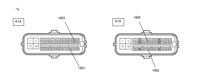
Standard Voltage Tester Connection Condition Specified Condition A14-43 (+BI1) - Body ground Always 11 to 14 V A16-38 (+BI2) - Body ground Always 11 to 14 V A14-29 (+BI3) - Body ground Always 11 to 14 V A16-22 (+BI4) - Body ground Always 11 to 14 V Text in Illustration *a Front view of wire harness connector
(to Skid Control ECU Assembly)
NG 
REPAIR OR REPLACE HARNESS OR CONNECTOR (+BI CIRCUIT)
OK 
-
-
RECONFIRM DTC
-
Reconnect the skid control ECU assembly connectors.
-
Clear the DTCs Click here.
-
Turn the power switch on (IG).
-
Check if the same DTC is output Click here.
Result Result Proceed to DTCs (C1311/11, C1312/12, C1313/13 and C1314/14) are not output A DTCs (C1311/11, C1312/12, C1313/13 and/or C1314/14) are output B
A
CHECK FOR INTERMITTENT PROBLEMS Click here
B
REPLACE SKID CONTROL ECU ASSEMBLY Click here
-