ELECTRONICALLY CONTROLLED BRAKE SYSTEM, Diagnostic DTC:C1249/49

| DTC Code | DTC Name |
|---|---|
| C1249/49 | Open in Stop Light Switch Circuit |
DESCRIPTION
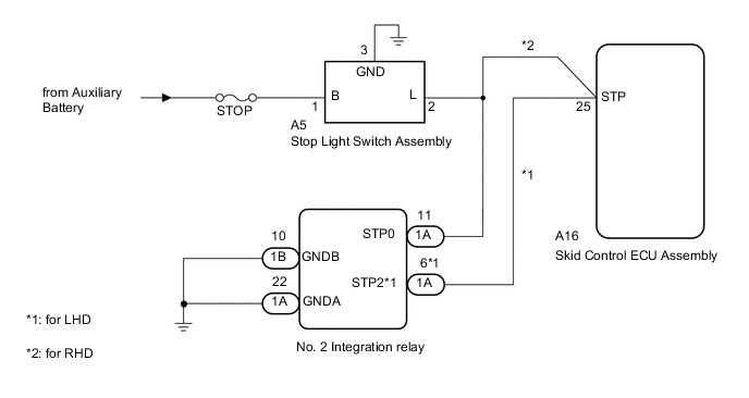
The skid control ECU assembly inputs the stop light switch signal and detects the brake pedal operation status.
The skid control ECU assembly has an open detection circuit, which outputs this DTC if it detects an open in the stop light input line or ground line of the stop light circuit with the stop light switch off (brake pedal not depressed).
| DTC Code | INF Code | DTC Detection Condition | Trouble Area |
|---|---|---|---|
| C1249/49 | 520 | When IG2 terminal voltage is 9.5 V or more, an open STP terminal circuit continues for 10 seconds or more. |
|
WIRING DIAGRAM
CAUTION / NOTICE / HINT
Note
When replacing the skid control ECU assembly, perform initialization and calibration of the linear solenoid valve Click here.
PROCEDURE
-
CHECK STOP LIGHT OPERATION
-
Check that the stop lights come on when the brake pedal is depressed, and go off when the brake pedal is released.
OK Condition Illumination Condition Brake pedal depressed ON Brake pedal released OFF
NG 
CHECK HARNESS AND CONNECTOR (SKID CONTROL ECU ASSEMBLY - STOP LIGHT SWITCH) Click here
OK 
-
-
CHECK HARNESS AND CONNECTOR (STP TERMINAL)
-
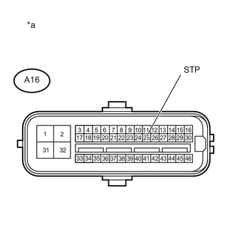
Text in Illustration *a Front view of wire harness connector
(to Skid Control ECU Assembly)
Turn the power switch off.
-
Make sure that there is no looseness at the locking part and the connecting part of the connector.
-
Disconnect the skid control ECU assembly connector.
-
Measure the voltage according to the value(s) in the table below.
Standard Voltage Tester Connection Switch Condition Specified Condition A16-25 (STP) - Body ground Stop light switch ON (Brake pedal depressed) 11 to 14 V A16-25 (STP) - Body ground Stop light switch OFF (Brake pedal released) Below 1.5 V Result Result Proceed to NG A OK (for LHD) B OK (for RHD) C
B
CHECK HARNESS AND CONNECTOR (NO. 2 INTEGRATION RELAY - SKID CONTROL ECU ASSEMBLY) Click here
C 
REPAIR OR REPLACE HARNESS OR CONNECTOR
A
-
-
INSPECT NO. 2 INTEGRATION RELAY
-
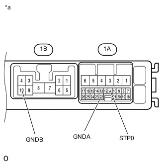
Text in Illustration *a Component without harness connected
(No. 2 Integration Relay)
Remove the No. 2 integration relay Click here.
-
Measure the resistance according to the value(s) in the table below.
Standard Resistance Tester Connection Condition Specified Condition 1A-11 (STP0) - 1A-22 (GNDA) Always 3 kΩ or less 1A-11 (STP0) - 1B-10 (GNDB) Always 3 kΩ or less
NG
REPLACE NO. 2 INTEGRATION RELAY Click here
OK
-
-
RECONFIRM DTC
-
Install the No. 2 integration relay Click here.
-
Reconnect the skid control ECU assembly connector.
-
Turn the power switch off.
-
Clear the DTCs Click here.
-
Turn the power switch on (READY).
-
Depress the brake pedal several times to test the stop light circuit.
-
Check if the same DTC is recorded Click here.
Result Result Proceed to DTC (C1249/49) is not output A DTC (C1249/49) is output B
A
CHECK FOR INTERMITTENT PROBLEMS Click here
B
REPLACE SKID CONTROL ECU ASSEMBLY Click here
-
-
CHECK HARNESS AND CONNECTOR (SKID CONTROL ECU ASSEMBLY - STOP LIGHT SWITCH)
-
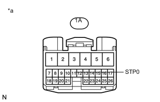
Text in Illustration *a Front view of wire harness connector
(to No. 2 Integration Relay)
Measure the voltage according to the value(s) in the table below.
Standard Voltage Tester Connection Condition Specified Condition 1A-11 (STP0) - Body ground Brake pedal depressed 11 to 14 V Brake pedal released Below 1.5 V
NG
REPAIR OR REPLACE HARNESS OR CONNECTOR
OK
-
-
INSPECT NO. 2 INTEGRATION RELAY
-
Reconnect the No. 2 integration relay connector.
-
Disconnect the A16 skid control ECU assembly connector.
-
Check that the stop lights come on when the brake pedal is depressed, and go off when the brake pedal is released.
OK Condition Illumination Condition Brake pedal depressed ON Brake pedal released OFF
OK
REPLACE SKID CONTROL ECU ASSEMBLY Click here
NG
REPLACE NO. 2 INTEGRATION RELAY Click here
-
-
CHECK HARNESS AND CONNECTOR (NO. 2 INTEGRATION RELAY - SKID CONTROL ECU ASSEMBLY)
-
Make sure that there is no looseness at the locking part and the connecting part of the connector.
-
Disconnect the A14 skid control ECU assembly connector.
-
Measure the resistance according to the value(s) in the table below.
Standard Resistance Tester Connection Condition Specified Condition 1A-3 (STOP) - A14-24 (STP2) Always Below 1 Ω 1A-3 (STOP) - Body ground Always 10 kΩ or higher
OK
REPLACE NO. 2 INTEGRATION RELAY Click here
NG
REPAIR OR REPLACE HARNESS OR CONNECTOR
-