REAR WHEEL ALIGNMENT ADJUSTMENT
CAUTION / NOTICE / HINT
Note
If the wheel alignment has been adjusted, or if suspension or underbody components have been removed/installed or replaced, be sure to perform the following initialization procedure in order for the system to function normally.
-
Disconnect the cable from the negative (-) battery terminal for more than 2 seconds.
-
Reconnect the cable to the negative (-) battery terminal.
-
Perform zero point calibration of the yaw rate and acceleration sensor and test mode inspection.
PROCEDURE
-
INSPECT TIRES
-
MEASURE VEHICLE HEIGHT
Note
Before inspecting wheel alignment, adjust vehicle height to the specified value.
-
INSPECT CAMBER
-
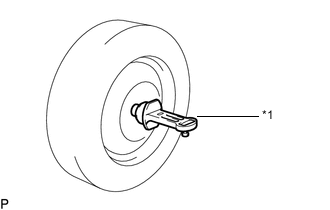
Text in Illustration *1 Gauge Install a camber-caster-kingpin gauge.
-
Inspect the camber.
CAMBER Camber for 2GR-FXE -1°29' +/-45'
(-1.48° +/-0.75°)
for 2AR-FSE -1°28' +/-45'
(-1.47° +/-0.75°)
Right-left error 45' (0.75°) or less If the measured value is not within the specified range, inspect the suspension parts for damage and wear. Replace parts as necessary because camber cannot be properly adjusted with any damaged or worn parts.
-
-
INSPECT TOE-IN
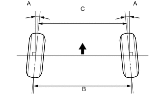
Text in Illustration 
Front of Vehicle Toe-in (Unloaded Vehicle) w/o Dynamic Rear Steering w/ Dynamic Rear Steering Except Korea A: 0°7.7' +/-5' (0.13° +/-0.09°)
B - C: 3 +/-2 mm (0.12 +/-0.08 in.)
A: 0°7.7' +/-5' (0.13° +/-0.09°)
B - C: 3 +/-2 mm (0.12 +/-0.08 in.)
for Korea A: 0°7.7' +/-5' (0.13° +/-0.09°)
B - C: 3 +/-2 mm (0.12 +/-0.08 in.)
A: 0°0' +/-5' (0.0° +/-0.09°)
B - C: 0 +/-2 mm (0.00 +/-0.08 in.)
If the toe-in is not within the specified range, inspect the suspension parts and replace if necessary.
-
ADJUST TOE-IN (w/o DYNAMIC REAR STEERING)
-
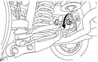
Loosen the toe adjust cam nut.
-
Turn the adjust cams by an equal amount to adjust toe-in.
Tech Tips
-
Try to adjust the toe-in to the center value.
-
The toe-in will change by the following specifications corresponding to each graduation of the cam.
Approx. 4.7 mm (0.19 in.)
-
-
Tighten the nut.
- Torque:
- 117 N*m { 1193 kgf*cm, 86 ft.*lbf }
-
-
ADJUST TOE-IN (w/ DYNAMIC REAR STEERING)
Note
If any underbody rear suspension parts are removed and installed, replaced or adjusted, the steering wheel may become off center. Therefore, perform neutral point memorization and motor rotation angle sensor calibration.
-
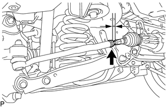
Measure the thread lengths of the right and left rack ends.
Standard Difference in thread length of 1.5 mm (0.059 in.) or less -
Remove the rack boot set clips.
-
Loosen the tie rod end lock nuts.
-
Adjust the rack ends if the difference in thread length between the right and left rack ends is not within the specified range.
-
Extend the shorter rack end if the measured toe-in deviates toward the inner-side.
-
Shorten the longer rack end if the measured toe-in deviates toward the outer-side.
-
-
Turn the right and left rack ends by an equal amount to adjust toe-in.
Tech Tips
Try to adjust toe-in to the center of the specified range.
-
Make sure that the lengths of the right and left rack ends are the same.
-
Tighten the tie rod end lock nuts.
- Torque:
- 55 N*m { 561 kgf*cm, 41 ft.*lbf }
Note
Temporarily tighten the lock nut while holding the hexagonal part of the steering rack end so that the lock nut and the steering rack end do not turn together. Hold the width across flat of the tie rod end and tighten the lock nut.
-
Place the boots on the seats and install the clips.
-
Perform neutral position memorization and motor rotation angle sensor calibration for the dynamic rear steering system Click here.
-
-
INSPECT REAR SUSPENSION
-
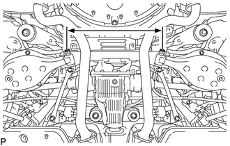
Inspect the rear suspension member.
-
Measure the distance between the centers of the installation bolts of the rear No. 2 suspension arm assembly LH and RH.
Standard 536.8 to 543.7 mm (1.761 to 1.783 ft.) Tech Tips
If the distance is not within the specified range, replace the rear suspension member.
-
-
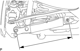
Inspect the rear No. 2 suspension arm assembly.
-
Measure the distance between the centers of the 2 installation bolts of the rear No. 2 suspension arm assembly.
Standard 433.5 to 434.5 mm (1.422 to 1.425 ft.) Tech Tips
If the distance is not within the specified range, replace the rear No. 2 suspension arm assembly.
-
-
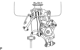
Inspect the rear upper control arm assembly.
-
Measure the distance between the centers of the installation bolt of the upper control arm assembly rear No. 2 and the ball joint stud.
Standard 299 mm (11.77 in.) Tech Tips
If the distance is not within the specified range, replace the rear upper control arm assembly.
-
-
Inspect and adjust toe-in and camber.
-
Inspect toe-in and camber.
If the values are not within the specified range, adjust the installation bolt holding the rear suspension member to the vehicle body, or the bolt holding the upper control arm and rear suspension arm so that the values fall within the specified range.
-
-
-
PLACE FRONT WHEELS FACING STRAIGHT AHEAD
-
REMOVE LUGGAGE COMPARTMENT FLOOR MAT
-
REMOVE LUGGAGE COMPARTMENT TRIM COVER LH
-
DISCONNECT CABLE FROM NEGATIVE AUXILIARY BATTERY TERMINAL
Note
Disconnect the cable from the negative (-) battery terminal for more than 2 seconds.
-
CONNECT CABLE TO NEGATIVE AUXILIARY BATTERY TERMINAL
Note
When disconnecting the cable, some systems need to be initialized after the cable is reconnected Click here.
-
INSTALL LUGGAGE COMPARTMENT TRIM COVER LH
-
INSTALL LUGGAGE COMPARTMENT FLOOR MAT
-
PERFORM YAW RATE AND ACCELERATION SENSOR ZERO POINT CALIBRATION
-
CHECK STEERING ANGLE SENSOR ZERO POINT CALIBRATION