REAR SUSPENSION MEMBER INSTALLATION

PROCEDURE
-
INSTALL REAR SUSPENSION MEMBER REAR BODY MOUNTING CUSHION (for LH Side)
-

Text in Illustration *a Soapy Water (Containing 20% Liquid Hand Soap) 
Front of Vehicle Apply diluted liquid soap to the outside of a new rear suspension member rear body mounting cushion.
Note
Do not use grease or undiluted liquid soap. Doing so may cause the rear suspension member rear body mounting cushion to slip out.
Tech Tips
A solution of soapy water containing 20% liquid hand soap is recommended.
-
Temporarily install the rear suspension member rear body mounting cushion while confirming the installation direction.
-

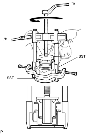
Text in Illustration *a Turn *b Hold Using SST, install the rear suspension member rear body mounting cushion so that there is no clearance between the suspension member sub-assembly and rear suspension member rear body mounting cushion.
- SST
- 09570-24011
- 09950-40011 ( 09951-04020, 09952-04010, 09953-04030, 09954-04020, 09955-04061, 09957-04010, 09958-04011 )
- 09950-60020 ( 09951-00910 )
Note
-
Apply grease to the threads and tip of SST center bolt before use.
-
Do not apply excessive pressure to the center sleeve of the rear suspension member rear body mounting cushion.
-
-
INSTALL REAR SUSPENSION MEMBER REAR BODY MOUNTING CUSHION (for RH Side)
Tech Tips
Use the same procedure described for the LH side.
-
INSTALL REAR SUSPENSION MEMBER REAR UPPER STOPPER (for LH Side)
-
Install the rear suspension member rear upper stopper to the rear suspension member sub-assembly.
-
-
INSTALL REAR SUSPENSION MEMBER REAR UPPER STOPPER (for RH Side)
Tech Tips
Use the same procedure described for the LH side.
-
INSTALL REAR SUSPENSION MEMBER FRONT BODY MOUNTING CUSHION (for LH Side)
-

Text in Illustration *a Soapy Water (Containing 20% Liquid Hand Soap) Front of Vehicle Apply diluted liquid soap to the outside of a new rear suspension member front body mounting cushion.
Note
Do not use grease or undiluted liquid soap. Doing so may cause the rear suspension member front body mounting cushion to slip out.
Tech Tips
A solution of soapy water containing 20% liquid hand soap is recommended.
-
Temporarily install the rear suspension member front body mounting cushion while confirming the installation direction.
-
Text in Illustration *a Turn *b Hold Using SST, install the rear suspension member front body mounting cushion so that there is no clearance between the suspension member sub-assembly and rear suspension member front body mounting cushion.
- SST
- 09316-12010
- 09570-24011
- 09950-40011 ( 09951-04020, 09952-04010, 09953-04030, 09954-04020, 09955-04061, 09957-04010, 09958-04011 )
- 09950-60020 ( 09951-00910 )
Note
-
Apply grease to the threads and tip of SST center bolt before use.
-
Do not apply excessive pressure to the center sleeve of the rear suspension member front body mounting cushion.
-
-
INSTALL REAR SUSPENSION MEMBER FRONT BODY MOUNTING CUSHION (for RH Side)
Tech Tips
Use the same procedure described for the LH side.
-
INSTALL REAR SUSPENSION MEMBER REAR LOWER STOPPER (for LH Side)
-
Install the rear suspension member rear lower stopper to the rear suspension member sub-assembly.
-
-
INSTALL REAR SUSPENSION MEMBER REAR LOWER STOPPER (for RH Side)
Tech Tips
Use the same procedure described for the LH side.
-
INSTALL REAR STABILIZER BAR
-
INSTALL REAR NO. 1 DIFFERENTIAL MOUNT CUSHION
-
INSTALL REAR NO. 2 DIFFERENTIAL MOUNT CUSHION
-
INSTALL REAR DIFFERENTIAL CARRIER ASSEMBLY
-
INSTALL PARKING BRAKE WITH BRACKET ACTUATOR ASSEMBLY
-
INSTALL REAR SUSPENSION MEMBER SUB-ASSEMBLY
-
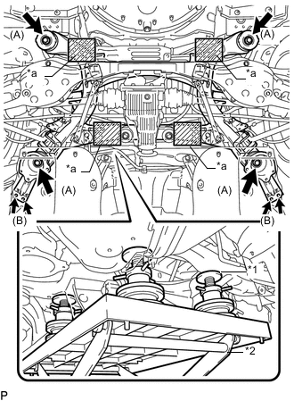
Text in Illustration *1 Attachment *2 Engine Lifter *a Attachment placement location Support the rear suspension member sub-assembly with an engine lifter using 4 attachments or equivalent tools.
Note
-
Make sure to secure the rear suspension member sub-assembly to prevent it from dropping.
-
Use the attachments to keep the rear suspension member sub-assembly level.
-
The rear suspension member sub-assembly is a heavy component. Make sure that it is supported securely.
-
-
Raise the rear suspension member sub-assembly until there is no clearance between the rear suspension member sub-assembly and the body.
Note
When raising the rear suspension member sub-assembly, be careful not to damage the vehicle body or other components installed on the vehicle.
-
Install the rear suspension member sub-assembly with the 2 rear suspension member lower stoppers, 2 rear suspension member lower stopper sub-assemblies and 6 bolts.
- Torque:
- for bolt A
- 127 N*m { 1295 kgf*cm, 94 ft.*lbf }
- for bolt B
- 19 N*m { 194 kgf*cm, 14 ft.*lbf }
-
Lower the engine lifter.
-
-
INSTALL REAR SUSPENSION MEMBER BRACE
-
Install the 2 rear suspension member braces with the 6 bolts.
- Torque:
- 19 N*m { 194 kgf*cm, 14 ft.*lbf }
-
-
INSTALL REAR AXLE ASSEMBLY LH
-
INSTALL REAR AXLE ASSEMBLY RH
Tech Tips
Use the same procedure described for the LH side.
-
TEMPORARILY INSTALL REAR UPPER CONTROL ARM ASSEMBLY LH
-
TEMPORARILY INSTALL REAR UPPER CONTROL ARM ASSEMBLY RH
Tech Tips
Use the same procedure described for the LH side.
-
TEMPORARILY INSTALL REAR NO. 1 UPPER CONTROL ARM ASSEMBLY (for LH Side)
-
TEMPORARILY INSTALL REAR NO. 1 UPPER CONTROL ARM ASSEMBLY (for RH Side)
Tech Tips
Use the same procedure described for the LH side.
-
TEMPORARILY INSTALL REAR NO. 2 SUSPENSION ARM ASSEMBLY LH
-
TEMPORARILY INSTALL REAR NO. 2 SUSPENSION ARM ASSEMBLY RH
Tech Tips
Use the same procedure described for the LH side.
-
INSTALL REAR SUSPENSION MEMBER BRACE LH
-
INSTALL REAR SUSPENSION MEMBER BRACE RH
Tech Tips
Use the same procedure described for the LH side.
-
TEMPORARILY INSTALL REAR SHOCK ABSORBER ASSEMBLY LH
-
TEMPORARILY INSTALL REAR SHOCK ABSORBER ASSEMBLY RH
Tech Tips
Use the same procedure described for the LH side.
-
INSTALL REAR STABILIZER LINK ASSEMBLY LH
-
INSTALL REAR STABILIZER LINK ASSEMBLY RH
Tech Tips
Use the same procedure described for the LH side.
-
TEMPORARILY INSTALL REAR NO. 1 SUSPENSION ARM ASSEMBLY LH
-
TEMPORARILY INSTALL REAR NO. 1 SUSPENSION ARM ASSEMBLY RH
Tech Tips
Use the same procedure described for the LH side.
-
TEMPORARILY INSTALL TOE CONTROL LINK SUB-ASSEMBLY LH (w/o DYNAMIC REAR STEERING)
-
TEMPORARILY INSTALL TOE CONTROL LINK SUB-ASSEMBLY RH (w/o DYNAMIC REAR STEERING)
Tech Tips
Use the same procedure described for the LH side.
-
INSTALL REAR STEERING LINK ASSEMBLY (w/ DYNAMIC REAR STEERING)
-
CONNECT REAR STEERING TIE ROD ASSEMBLY LH (w/ DYNAMIC REAR STEERING)
-
CONNECT REAR STEERING TIE ROD ASSEMBLY RH (w/ DYNAMIC REAR STEERING)
Tech Tips
Use the same procedure described for the LH side.
-
INSTALL PARKING BRAKE
-
INSTALL REAR AXLE SHAFT NUT LH
-
INSTALL REAR AXLE SHAFT NUT RH
Tech Tips
Use the same procedure described for the LH side.
-
INSPECT REAR AXLE HUB AND BEARING LOOSENESS
-
INSPECT REAR AXLE HUB RUNOUT
-
INSTALL REAR AXLE SHAFT NUT LH
-
INSTALL REAR AXLE SHAFT NUT RH
Tech Tips
Use the same procedure described for the LH side.
-
INSTALL REAR SPEED SENSOR LH
-
INSTALL REAR SPEED SENSOR RH
Tech Tips
Use the same procedure described for the LH side.
-
STABILIZE SUSPENSION
-
TIGHTEN REAR UPPER CONTROL ARM ASSEMBLY LH
-
TIGHTEN REAR UPPER CONTROL ARM ASSEMBLY RH
Tech Tips
Use the same procedure described for the LH side.
-
TIGHTEN REAR NO. 1 UPPER CONTROL ARM ASSEMBLY (for LH Side)
-
TIGHTEN REAR NO. 1 UPPER CONTROL ARM ASSEMBLY (for RH Side)
Tech Tips
Use the same procedure described for the LH side.
-
TIGHTEN REAR NO. 2 SUSPENSION ARM ASSEMBLY LH
-
TIGHTEN REAR NO. 2 SUSPENSION ARM ASSEMBLY RH
Tech Tips
Use the same procedure described for the LH side.
-
TIGHTEN REAR SHOCK ABSORBER ASSEMBLY LH
-
TIGHTEN REAR SHOCK ABSORBER ASSEMBLY RH
Tech Tips
Use the same procedure described for the LH side.
-
TIGHTEN REAR NO. 1 SUSPENSION ARM ASSEMBLY LH
-
TIGHTEN REAR NO. 1 SUSPENSION ARM ASSEMBLY RH
Tech Tips
Use the same procedure described for the LH side.
-
TIGHTEN TOE CONTROL LINK SUB-ASSEMBLY LH (w/o DYNAMIC REAR STEERING)
-
TIGHTEN TOE CONTROL LINK SUB-ASSEMBLY RH (w/o DYNAMIC REAR STEERING)
Tech Tips
Use the same procedure described for the LH side.
-
INSTALL REAR SUSPENSION ARM COVER LH
-
INSTALL REAR SUSPENSION ARM COVER RH
Tech Tips
Use the same procedure described for the LH side.
-
INSTALL REAR HEIGHT CONTROL SENSOR SUB-ASSEMBLY
-
INSTALL PROPELLER WITH CENTER BEARING SHAFT ASSEMBLY
-
CONNECT PARKING BRAKE CABLE
-
INSTALL ELECTRIC PARKING BRAKE ACTUATOR CAP
-
INSTALL PARKING BRAKE CABLE HEAT INSULATOR
-
INSTALL NO. 1 FLOOR UNDER COVER
-
CONNECT WIRE HARNESS
-
CONNECT CABLE TO NEGATIVE AUXILIARY BATTERY TERMINAL
-
INSTALL LUGGAGE COMPARTMENT TRIM COVER LH
-
INSTALL LUGGAGE COMPARTMENT FLOOR MAT
-
ADJUST PARKING BRAKE
-
INSTALL REAR WHEEL
-
PERFORM INITIALIZATION
-
PERFORM PARKING BRAKE SHOE BEDDING
-
CALIBRATE STEERING SENSOR
-
INSPECT AND ADJUST REAR WHEEL ALIGNMENT
-
HEADLIGHT AIMING ADJUSTMENT
-
for Triple Beam Headlight:
-
for Single Beam Headlight:
-
-
CHECK SPEED SENSOR SIGNAL