DYNAMIC RADAR CRUISE CONTROL SYSTEM, Diagnostic DTC:C1A4A
| DTC Code | DTC Name |
|---|---|
| C1A4A | Skid Control Buzzer Circuit |
DESCRIPTION
Based on dynamic radar cruise control system operation, the driving support ECU assembly provides warnings to the driver by sounding the skid control buzzer assembly.
DTC C1A4A is stored when a malfunction is detected in the skid control buzzer assembly circuit.
| DTC No. | DTC Detection Condition | Trouble Area |
|---|---|---|
| C1A4A |
w/o Full-speed range following function:
w/ Full-speed range following function: |
|
WIRING DIAGRAM
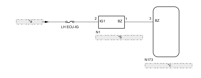
| *a | from IG Circuit |
| *b | Skid Control Buzzer Assembly |
| *c | Driving Support ECU Assembly |
CAUTION / NOTICE / HINT
Note
-
Inspect the fuses for circuits related to this system before performing the following procedure.
-
When replacing the driving support ECU assembly, always replace it with a new one. If a driving support ECU assembly which was installed to another vehicle is used, the information stored in the driving support ECU assembly will not match the information from the vehicle. As a result, a DTC may be stored.
PROCEDURE
-
PERFORM ACTIVE TEST USING GTS (RADAR CRUISE APPROACH ALARM BUZZER)
-
Connect the GTS to the DLC3.
-
Turn the power switch on (IG).
-
Turn the GTS on.
-
Enter the following menus: Powertrain / Radar Cruise / Active Test.
-
Perform the Active Test according to the display on the GTS.
Radar Cruise Tester Display Test Part Control Range Diagnostic Note Radar Cruise Approach Alarm Buzzer Skid control buzzer assembly ON or OFF Buzzer can be heard OK Skid control buzzer assembly sounds.
NG 
CHECK TERMINAL VOLTAGE Click here
OK 
-
-
CHECK FOR DTCs
-
Clear the DTCs Click here.
-
Make sure that the DTC detection conditions are met.
Tech Tips
If the detection conditions are not met, the system cannot detect the malfunction.
-
Turn the power switch on (IG).
-
Turn the dynamic radar cruise control system on using the cruise control main switch (ON/OFF).
-
w/ Full-speed range following function: Drive the vehicle at 5 km/h (3 mph) or more for 0.4 seconds or more.
w/o Full-speed range following function: Drive the vehicle at 36 km/h (22 mph) or more for 0.4 seconds or more.
-
-
Check for DTCs Click here.
Result Result Proceed to DTC C1A4A is output A DTC C1A4A is not output B
A 
REPLACE DRIVING SUPPORT ECU ASSEMBLY Click here
B
USE SIMULATION METHOD TO CHECK Click here
-
-
CHECK TERMINAL VOLTAGE
-
Disconnect the E5 skid control buzzer assembly connector.
-
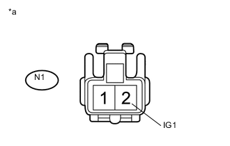
Text in Illustration *a Front view of wire harness connector
(to Skid Control Buzzer Assembly)
Measure the voltage according to the value(s) in the table below.
Standard Voltage Tester Connection Condition Specified Condition N1-2 (IG1) - Body ground Power switch on (IG) 11 to 14 V N1-2 (IG1) - Body ground Power switch off Below 1 V
NG
REPAIR OR REPLACE HARNESS OR CONNECTOR
OK
-
-
INSPECT SKID CONTROL BUZZER ASSEMBLY (UNIT INSPECTION)
-
Remove the skid control buzzer assembly Click here.
-
Inspect the skid control buzzer assembly Click here.
Result Result Proceed to Skid control buzzer assembly is normal. A Skid control buzzer assembly is abnormal. B
B
REPLACE SKID CONTROL BUZZER ASSEMBLY Click here
A
-
-
CHECK HARNESS AND CONNECTOR (SKID CONTROL BUZZER ASSEMBLY - DRIVING SUPPORT ECU ASSEMBLY)
-
Disconnect the N1 skid control buzzer assembly connector.
-
Disconnect the N173 driving support ECU assembly connector.
-
Measure the resistance according to the value(s) in the table below.
Standard Resistance Tester Connection Condition Specified Condition N1-1 (BZ) - N173-3 (BZ) Always Below 1 Ω N1-1 (BZ) or N173-3 (BZ) - Body ground Always 10 kΩ or higher
OK
REPLACE DRIVING SUPPORT ECU ASSEMBLY Click here
NG
REPAIR OR REPLACE HARNESS OR CONNECTOR
-