WATER PUMP INSTALLATION

PROCEDURE
-
INSTALL ENGINE WATER PUMP ASSEMBLY
-
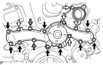
Install a new water pump gasket and the engine water pump with the 16 bolts.
- Torque:
- for bolt A
- 21 N*m { 214 kgf*cm, 15 ft.*lbf }
- for bolt B, C
- 11 N*m { 112 kgf*cm, 8 ft.*lbf }
Text in Illustration 
Bolt A 
Bolt B 
Bolt C Note
-
Be sure to apply adhesive to the 2 bolts labeled C before reusing them, or replace them with new ones if necessary.
Adhesive Toyota Genuine Adhesive 1344, Three Bond 1344 or equivalent -
Make sure that there is no oil on the threads of the bolts labeled A.
Standard Length Item Length Bolt A 55 mm (2.17 in.) Bolt B, C 22 mm (0.87 in.)
-
-
INSTALL WATER INLET ASSEMBLY
-
Install a new No. 1 water inlet housing gasket and water outlet pipe O-ring.
-
Install the water inlet assembly with the 4 bolts and nut.
- Torque:
- 10 N*m { 102 kgf*cm, 7 ft.*lbf }
Note
Be careful not to allow the O-ring to get caught between parts.
-
Connect the 4 hoses.
-
-
INSTALL WATER PUMP PULLEY
-
Temporarily install the pulley with the 4 bolts.
-
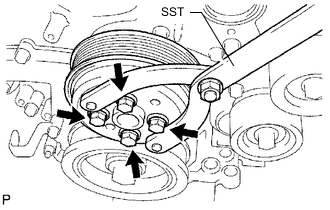
Using SST, hold the pulley and tighten the 4 bolts.
- SST
- 09960-10010 ( 09962-01000, 09963-00700 )
- Torque:
- 21 N*m { 214 kgf*cm, 15 ft.*lbf }
-
-
INSTALL NO. 2 ENGINE COVER
-
INSTALL INJECTOR DRIVER
-
INSTALL NO. 1 ENGINE COVER
-
CONNECT NO. 2 RADIATOR HOSE
-
INSTALL NO. 1 RADIATOR HOSE
-
INSTALL V-RIBBED BELT TENSIONER ASSEMBLY
-
INSTALL COMPRESSOR WITH MOTOR ASSEMBLY
-
CONNECT NO. 1 COOLER REFRIGERANT DISCHARGE HOSE
-
CONNECT SUCTION HOSE
-
INSTALL FAN AND GENERATOR V BELT
-
INSTALL ECM
-
INSTALL SERVICE PLUG GRIP
-
INSTALL LOWER HYBRID VEHICLE BATTERY COVER PANEL
-
INSTALL NO. 1 SEAT ARMREST CAP
-
CONNECT CABLE TO NEGATIVE AUXILIARY BATTERY TERMINAL
Note
When disconnecting the cable, some systems need to be initialized after the cable is reconnected Click here.
-
INSTALL LUGGAGE COMPARTMENT TRIM COVER LH
-
INSTALL LUGGAGE COMPARTMENT FLOOR MAT
-
ADD ENGINE COOLANT
-
CHARGE AIR CONDITIONING SYSTEM WITH REFRIGERANT
-
INSPECT FOR COOLANT LEAK
-
WARM UP COMPRESSOR
-
CHECK FOR REFRIGERANT GAS LEAK
-
INSTALL REAR ENGINE UNDER COVER LH
-
INSTALL ENGINE UNDER COVER
-
INSTALL NO. 1 AIR CLEANER INLET
-
INSTALL COOL AIR INTAKE DUCT SEAL
-
INSTALL ENGINE ROOM SIDE COVER
-
INSTALL V-BANK COVER SUB-ASSEMBLY
-
PERFORM INITIALIZATION