INTAKE MANIFOLD INSTALLATION
PROCEDURE
-
INSTALL STUD BOLT
Note
If a stud bolt is deformed or its threads are damaged, replace it.
-
Using the E6 and E8 "TORX" socket wrench, install the stud bolts.
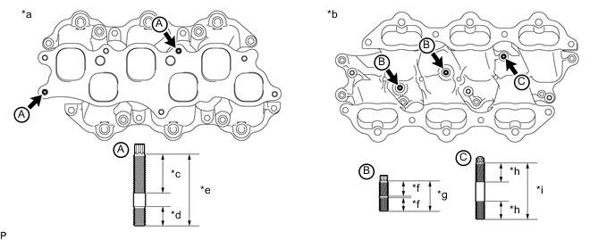
Text in Illustration *a Upper Side *b Lower Side *c 26 mm (1.02 in.) *d 13 mm (0.512 in.) *e 48 mm (1.89 in.) *f 9 mm (0.354 in.) *g 19 mm (0.748 in.) *h 12 mm (0.472 in.) *i 37 mm (1.46 in.) - - - Torque:
- for stud bolt A
- 10 N*m { 102 kgf*cm, 7 ft.*lbf }
- for stud bolt B and C
- 4.0 N*m { 41 kgf*cm, 35 in.*lbf }
-
-
INSTALL WIRE HARNESS
-
Install the wire harness with the bolt.
- Torque:
- 10 N*m { 102 kgf*cm, 7 ft.*lbf }
-
Attach the 2 clamps.
-
-
INSTALL SOLENOID VALVE ASSEMBLY
-
INSTALL INTAKE MANIFOLD
-
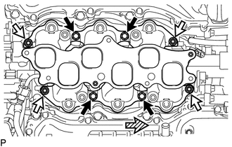
Install 2 new gaskets and the intake manifold with the 4 bolts and 4 nuts.
- Torque:
- 21 N*m { 214 kgf*cm, 15 ft.*lbf }
Text in Illustration 
Bolt 
Nut 
Front -
Install the fuel tube Click here.
-
Apply engine oil to the threads of the union bolt.
-
Install a new gasket to the fuel tube, and then connect the fuel tube to the fuel pump with the union bolt.
- Torque:
- 23 N*m { 235 kgf*cm, 17 ft.*lbf }
-
Attach the connector to the intake manifold.
-
-
INSTALL FUEL DELIVERY PIPE SUB-ASSEMBLY
-
INSTALL INTAKE AIR SURGE TANK ASSEMBLY
Note
Do not apply oil to the bolts for the parts listed below:
Part Intake air surge tank assembly and intake manifold No. 2 surge tank stay and intake air surge tank assembly
-
Connect the water by-pass hose clamp.
-
Install a new gasket to the intake air surge tank assembly.
-
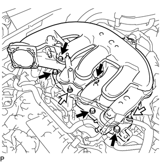
Install the intake air surge tank assembly with the 2 nuts and 5 bolts.
- Torque:
- 21 N*m { 214 kgf*cm, 15 ft.*lbf }
Text in Illustration Bolt Nut -
Install the No. 2 surge tank stay with the bolt.
- Torque:
- 21 N*m { 214 kgf*cm, 15 ft.*lbf }
-
Install the No. 3 water by-pass pipe with the bolt.
- Torque:
- 10 N*m { 102 kgf*cm, 7 ft.*lbf }
-
Connect the No. 2 water by-pass hose to the intake air surge tank assembly.
-
Connect the PCV hose.
-
Connect the connector.
-
Connect the 3 wire harness clamps.
-
Attach the 2 wire harness clamps.
-
Install the nut.
- Torque:
- 10 N*m { 102 kgf*cm, 7 ft.*lbf }
-
-
INSTALL PURGE VSV
-
INSTALL MANIFOLD ABSOLUTE PRESSURE SENSOR
-
INSTALL THROTTLE BODY WITH MOTOR ASSEMBLY
-
INSTALL COWL TOP VENTILATOR LOUVER SUB-ASSEMBLY
-
CONNECT CABLE TO NEGATIVE AUXILIARY BATTERY TERMINAL
Note
When disconnecting the cable, some systems need to be initialized after the cable is reconnected Click here.
-
INSTALL LUGGAGE COMPARTMENT TRIM COVER LH
-
INSTALL LUGGAGE COMPARTMENT FLOOR MAT
-
INSPECT FOR FUEL LEAK