ENGINE ASSEMBLY INSTALLATION
CAUTION / NOTICE / HINT
CAUTION:
As the engine assembly with transmission is extremely heavy, the engine lifter may suddenly drop if the instructions listed in the repair manual are not followed. Therefore, always follow the instructions listed in the repair manual when performing this procedure.
PROCEDURE
-
INSTALL REAR NO. 1 ENGINE MOUNTING INSULATOR
Tech Tips
Only perform this procedure when replacement of the engine mounting insulator is necessary.
-
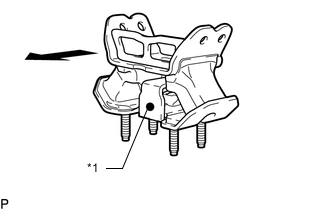
Text in Illustration *1 Paint Mark 
Rear of Vehicle Install the rear No. 1 engine mounting insulator to the hybrid vehicle transmission assembly with the 4 bolts.
- Torque:
- 52 N*m { 530 kgf*cm, 38 ft.*lbf }
Tech Tips
Make sure that the paint mark faces toward the rear of the vehicle.
-
-
INSTALL FRONT ENGINE MOUNTING INSULATOR
Tech Tips
Only perform this procedure when replacement of the engine mounting insulator is necessary.
-
Install the front engine mounting insulator RH and LH with the 2 nuts.
- Torque:
- 70 N*m { 714 kgf*cm, 52 ft.*lbf }
-
-
INSTALL ENGINE HANGER
-
REMOVE ENGINE STAND
-
Attach an engine sling device and hang the engine with a chain block.
Note
Pay attention to the angle of the sling device as the engine assembly or engine hangers may be damaged or deformed if the angle is incorrect.
-
Lift the engine and remove it from the engine stand.
Note
With the exception of installing the engine assembly to an engine stand or removing the engine assembly from an engine stand, do not perform any work on the engine while it is suspended, as doing so is dangerous.
-
Place the engine onto a work bench.
-
-
INSTALL FRONT SUSPENSION CROSSMEMBER SUB-ASSEMBLY
-
Install the front suspension crossmember sub-assembly with the 2 bolts.
- Torque:
- 35 N*m { 357 kgf*cm, 26 ft.*lbf }
-
-
INSTALL FAN AND GENERATOR V BELT
-
INSTALL COMPRESSOR WITH MOTOR ASSEMBLY
-
INSTALL FLYWHEEL SUB-ASSEMBLY
-
INSTALL TRANSMISSION INPUT DAMPER COVER ASSEMBLY
-
INSTALL HYBRID VEHICLE TRANSMISSION ASSEMBLY
-
INSTALL FLYWHEEL HOUSING SIDE COVER
-
INSTALL STARTER HOLE INSULATOR
-
INSTALL TRANSMISSION BREATHER HOSE SUB-ASSEMBLY
-
INSTALL WATER PIPE AND HOSE SUB-ASSEMBLY
-
INSTALL OIL COOLER HOSE TUBE SUB-ASSEMBLY
-
CONNECT WIRE HARNESS
-
CONNECT CONNECTOR
-
INSTALL REAR ENGINE MOUNTING MEMBER
-
Install the engine rear mounting member to the hybrid vehicle transmission assembly with the 4 nuts.
- Torque:
- 13 N*m { 133 kgf*cm, 10 ft.*lbf }
-
-
INSTALL EXHAUST MANIFOLD SUB-ASSEMBLY LH
-
INSTALL EXHAUST MANIFOLD SUB-ASSEMBLY RH
-
INSTALL ENGINE UNDER COVER SUB-ASSEMBLY LH
-
Install the engine under cover sub-assembly LH.
-
-
INSTALL ENGINE UNDER COVER SUB-ASSEMBLY RH
-
Install the engine under cover sub-assembly RH.
-
-
INSTALL ENGINE OIL LEVEL DIPSTICK GUIDE
-
Install a new O-ring to the engine oil level dipstick guide.
-
Apply a light coat of engine oil to the O-ring.
-
Push in the engine oil level dipstick guide end into the guide hole.
-
Install the engine oil level dipstick guide with the bolt.
- Torque:
- 10 N*m { 102 kgf*cm, 7 ft.*lbf }
-
-
INSTALL NO. 2 ENGINE OIL LEVEL DIPSTICK GUIDE
-
INSTALL ENGINE AND TRANSMISSION ASSEMBLY
-
Set the engine on an engine lifter.
Note
-
Place wooden blocks or plate lift attachments so that the engine is level.
-
With the exception of installing the engine assembly to an engine stand or removing the engine assembly from an engine stand, do not perform any work on the engine while it is suspended, as doing so is dangerous.
-
Never install attachments to the oil pan of the engine assembly or transmission as doing so may deform the oil pan.
-
-
Remove the 4 bolts and 2 No. 1 engine hangers.
-
Operate the engine lifter and install the engine to the vehicle.
Note
Make sure that the engine is clear of all wiring and hoses.
-
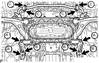
Install the engine and transmission assembly with crossmember with the 6 bolts, 4 new bolts and 2 nuts.
- Torque:
- for bolt A
- 194 N*m { 1978 kgf*cm, 143 ft.*lbf }
- for bolt B
- 57 N*m { 581 kgf*cm, 42 ft.*lbf }
- for bolt C
- 49 N*m { 500 kgf*cm, 36 ft.*lbf }
- for nut
- 151 N*m { 1540 kgf*cm, 111 ft.*lbf }
Text in Illustration Bolt 
Nut -
Install the rear engine mounting member with the 4 bolts.
- Torque:
- 35 N*m { 354 kgf*cm, 26 ft.*lbf }
-
Connect the wire harness with the nut.
- Torque:
- 5.4 N*m { 55 kgf*cm, 48 in.*lbf }
-
-
INSTALL FRONT LOWER SUSPENSION MEMBER PROTECTOR
-
Install the front lower suspension member protector with the 4 bolts.
- Torque:
- 5.5 N*m { 56 kgf*cm, 49 in.*lbf }
-
-
INSTALL FRONT NO. 2 UPPER SUSPENSION MEMBER
-
Install the 2 front No. 2 upper suspension members with the 6 bolts.
- Torque:
- 20 N*m { 204 kgf*cm, 15 ft.*lbf }
-
-
CONNECT FLOOR SHIFT GEAR SHIFTING ROD SUB-ASSEMBLY
-
CONNECT POWER STEERING LINK WIRE HARNESS
-
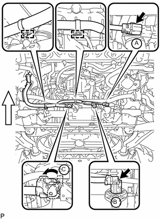
Connect the wire harness connector (C) to the power steering link assembly and securely lock the connector.
Text in Illustration Front -
Connect the 2 wire harness connectors (A) and (B) to the power steering link assembly.
-
Connect the 2 wire harness clamps to the bracket.
-
-
CONNECT FRONT LOWER BALL JOINT ASSEMBLY LH
-
CONNECT FRONT LOWER BALL JOINT ASSEMBLY RH
Tech Tips
Install the RH side following the same procedure as for the LH side.
-
CONNECT FRONT SHOCK ABSORBER ASSEMBLY LH
-
Connect the lower part of the front shock absorber assembly LH to the front lower suspension arm assembly with the bolt and nut.
- Torque:
- 108 N*m { 1101 kgf*cm, 80 ft.*lbf }
Note
-
Insert the bolt from the rear of the vehicle.
-
When tightening the bolt, keep the nut from rotating.
-
-
CONNECT FRONT SHOCK ABSORBER ASSEMBLY RH
Tech Tips
Install the RH side following the same procedure as for the LH side.
-
CONNECT STEERING SLIDING WITH SHAFT YOKE SUB-ASSEMBLY (w/o VGRS)
-
CONNECT STEERING SLIDING WITH SHAFT YOKE SUB-ASSEMBLY (w/ VGRS)
-
INSTALL PROPELLER WITH CENTER BEARING SHAFT ASSEMBLY
-
FULLY TIGHTEN NO. 1 CENTER SUPPORT BEARING ASSEMBLY
-
INSPECT AND ADJUST NO. 2 AND NO. 3 JOINT ANGLE
-
INSTALL FRONT NO. 1 FLOOR HEAT INSULATOR
-
INSTALL NO. 1 FUEL TANK PROTECTOR
-
INSTALL FRONT CENTER FLOOR BRACE SUB-ASSEMBLY
-
Install the front center floor brace sub-assembly with the 4 bolts.
- Torque:
- 7.4 N*m { 75 kgf*cm, 65 in.*lbf }
-
-
INSTALL NO. 1 EXHAUST PIPE SUPPORT BRACKET SUB-ASSEMBLY
-
INSTALL FRONT EXHAUST PIPE ASSEMBLY
-
CONNECT HEATED OXYGEN SENSOR (for Bank 2 Sensor 2)
-
CONNECT HEATED OXYGEN SENSOR (for Bank 1 Sensor 2)
-
INSTALL FRONT CENTER FLOOR BRACE
-
INSTALL NO. 2 REAR FLOOR BOARD SUB-ASSEMBLY
-
INSTALL NO. 1 REAR FLOOR BOARD SUB-ASSEMBLY
-
CONNECT ENGINE WIRE
-
Engine Room LH Side:
-
Connect the No. 2 connector holder with the clamp and 3 claws.
-
Connect the 3 connectors from the No. 2 connector holder.
-
Install the No. 1 engine room relay block cover.
-
-
Engine Room RH Side:
-
Install the bolt, clamp and No. 3 engine wire.
- Torque:
- 8.5 N*m { 87 kgf*cm, 75 in.*lbf }
-
-
-
CONNECT INVERTER RESERVOIR TANK ASSEMBLY (for LHD)
-
CONNECT INVERTER RESERVOIR TANK ASSEMBLY (for RHD)
-
CONNECT MOTOR CABLE
-
CONNECT GENERATOR CABLE
-
INSTALL ECM
-
CONNECT SUCTION HOSE
-
CONNECT NO. 1 COOLER REFRIGERANT DISCHARGE HOSE
-
INSTALL NO. 1 INVERTER COOLING PIPE (for LHD)
-
Install the No. 1 inverter cooling pipe with the bolt.
- Torque:
- 13 N*m { 127 kgf*cm, 9 ft.*lbf }
-
Connect the 2 hoses.
-
Connect the 2 connectors and 2 wire harness clamps.
-
-
CONNECT NO. 7 INVERTER COOLING HOSE (for RHD)
-
Connect the No. 7 inverter cooling hose.
-
-
CONNECT NO. 5 INVERTER COOLING HOSE (for LHD)
-
Connect the No. 5 inverter cooling hose.
-
-
CONNECT NO. 2 MOTOR COOLING HOSE (for RHD)
-
Connect the No. 2 motor cooling hose.
-
-
CONNECT NO. 2 OIL COOLER OUTLET HOSE
-
CONNECT NO. 2 OIL COOLER INLET HOSE
-
CONNECT AIR CONDITIONING HARNESS
-
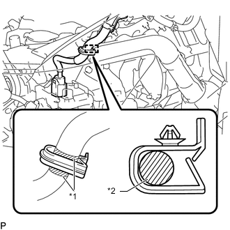
Text in Illustration *1 White Tape *2 Air Conditioning Harness Connect the white tape part of the air conditioning harness to the clamp as shown in the illustration.
Note
Make sure that the air conditioning harness is securely connected.
-
Connect the 2 wire harness clamps to each bracket.
-
Connect the bracket with the bolt.
- Torque:
- 10 N*m { 102 kgf*cm, 7 ft.*lbf }
-
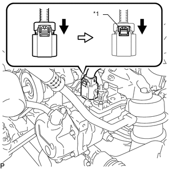
Text in Illustration *1 Green-colored Lock Connect the connector and lock the green-colored lock as shown in the illustration.
CAUTION:
Wear insulated gloves when performing the procedure.
-
-
CONNECT OUTLET HEATER WATER HOSE
-
Connect the outlet heater water hose.
-
Install the water hose set.
-
-
CONNECT INLET HEATER WATER HOSE
-
Connect the inlet heater water hose.
-
Install the water hose set.
-
-
CONNECT NO. 2 RADIATOR HOSE
-
INSTALL NO. 1 RADIATOR HOSE
-
CONNECT FUEL TUBE SUB-ASSEMBLY
-
Connect the fuel tube sub-assembly Click here.
-
-
CONNECT NO. 2 FUEL TUBE SUB-ASSEMBLY
-
Connect the No. 2 fuel tube sub-assembly Click here.
-
-
CONNECT NO. 3 FUEL TUBE SUB-ASSEMBLY
-
Connect the No. 3 fuel tube sub-assembly Click here.
-
-
CONNECT PURGE LINE HOSE
-
Install the clamp and connect the purge line hose.
-
-
INSTALL HEATER ACCESSORY ASSEMBLY
-
CONNECT WIRING HARNESS PROTECTOR
-
INSTALL OIL PUMP MOTOR CONTROLLER
-
CONNECT WIRE HARNESS
-
INSTALL AIR CLEANER CASE SUB-ASSEMBLY
-
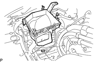
Text in Illustration *1 Pin *2 Grommet Insert the pin on the lower side of the air cleaner case into the grommet.
-
Install the air cleaner case, 2 clamps and 2 bolts.
- Torque:
- 5.0 N*m { 51 kgf*cm, 44 in.*lbf }
Note
During removal, do not lose the grommet on the underside of the air cleaner case.
-
-
INSTALL AIR CLEANER FILTER ELEMENT SUB-ASSEMBLY
-
INSTALL AIR CLEANER CAP WITH AIR CLEANER HOSE
-
INSTALL NO. 1 AIR CLEANER INLET
-
Install the No. 1 air cleaner inlet with the bolt.
- Torque:
- 5.0 N*m { 51 kgf*cm, 44 in.*lbf }
-
-
ADD ENGINE OIL
-
INSTALL CONNECTOR COVER ASSEMBLY
-
INSTALL INVERTER TERMINAL COVER
-
INSTALL INVERTER MOTOR CABLE BRACKET ASSEMBLY
-
INSTALL INVERTER COVER
-
INSTALL SERVICE PLUG GRIP
-
INSTALL LOWER HYBRID VEHICLE BATTERY COVER PANEL
-
INSTALL NO. 1 SEAT ARMREST CAP
-
CONNECT CABLE TO NEGATIVE AUXILIARY BATTERY TERMINAL
Note
When disconnecting the cable, some systems need to be initialized after the cable is reconnected Click here.
-
INSTALL LUGGAGE COMPARTMENT TRIM COVER LH
-
INSTALL LUGGAGE COMPARTMENT FLOOR MAT
-
PERFORM INITIALIZATION
-
ADJUST SHIFT LEVER POSITION
-
INSPECT SHIFT LEVER POSITION
-
ADD ENGINE COOLANT
-
ADD COOLANT (for Inverter)
-
CHARGE AIR CONDITIONING SYSTEM WITH REFRIGERANT (for HFC-134a(R134a))
-
INSPECT FOR COOLANT LEAK
-
INSPECT COOLANT LEAK (for Inverter)
-
INSPECT FOR OIL LEAK
-
INSPECT FOR FUEL LEAK
-
INSPECT FOR EXHAUST GAS LEAK
-
CHECK FOR REFRIGERANT GAS LEAK (for HFC-134a(R134a))
-
INSTALL FRONT WHEEL
- Torque:
- 103 N*m { 1050 kgf*cm, 76 ft.*lbf }
-
PLACE FRONT WHEELS FACING STRAIGHT AHEAD
-
CHECK AND ADJUST FRONT WHEEL ALIGNMENT
-
VARIABLE GEAR RATIO STEERING SYSTEM CALIBRATION (w/ VGRS)
-
ADJUST MILLIMETER WAVE RADAR SENSOR ASSEMBLY (w/ Dynamic Radar Cruise Control System)
-
INSPECT THROTTLE WITH MOTOR BODY ASSEMBLY
-
INSPECT IGNITION TIMING
-
INSPECT ENGINE IDLE SPEED
-
INSPECT CO/HC
-
INSPECT ENGINE COOLANT LEVEL
-
INSPECT COOLANT LEVEL IN RESERVOIR TANK (for Inverter)
-
INSPECT ENGINE OIL LEVEL
-
INSTALL NO. 2 ENGINE UNDER COVER
-
Install the No. 2 engine under cover with the 4 screws and 2 grommets.
-
-
INSTALL FRONT SUSPENSION MEMBER BRACE
-
w/ Canister Pump Module:
Install the front suspension member brace with the 6 bolts.
- Torque:
- 52 N*m { 530 kgf*cm, 38 ft.*lbf }
-
w/o Canister Pump Module:
Install the front suspension member brace with the clip and 4 bolts.
- Torque:
- 52 N*m { 530 kgf*cm, 38 ft.*lbf }
-
-
INSTALL REAR ENGINE UNDER COVER LH
-
Install the rear engine under cover LH with the screw.
-
-
INSTALL REAR ENGINE UNDER COVER RH
Tech Tips
Install the RH side following the same procedure as for the LH side.
-
INSTALL ENGINE UNDER COVER
-
Install the engine under cover with the 13 screws and 3 clips.
-
-
INSTALL V-BANK COVER SUB-ASSEMBLY
-
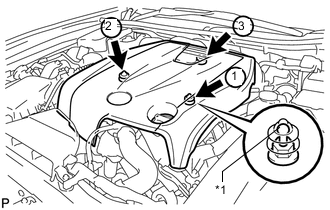
Text in Illustration *1 Tip (Round Portion) Attach the 3 clips in the order shown in the illustration to install the V-bank cover.
Note
-
Securely attach the clips.
-
If the clips are forcibly attached or struck with an object, they may be damaged.
-
Do not apply any oil to the tips (round portions).
-
-
-
INSTALL COOL AIR INTAKE DUCT SEAL
-
Install the cool air intake duct seal with the 7 clips.
-
-
INSTALL ENGINE ROOM SIDE COVER
-
Install the engine room side cover with the 4 clips.
-