HV BATTERY INSTALLATION

PROCEDURE
-
PRECAUTION
-
When disposing of an HV battery, make sure to return it through an authorized collection agent who is capable of handling it safely. If the HV battery is returned via the manufacturer specified route, it will be returned properly and in a safe manner by an authorized collection agent.
CAUTION:
-
Accidents such as electric shock may result if the HV battery is disposed of improperly or abandoned. Therefore, make sure to return all HV batteries through an authorized collection agent.
-
After removing the HV battery, keep it away from water. Exposure to water may cause the HV battery to produce heat, resulting in a fire.
-
-
-
INSTALL NO. 5 HYBRID BATTERY INTAKE DUCT
CAUTION:
Wear insulated gloves.
-
Install the No. 5 hybrid battery intake duct.
-
-
INSTALL NO. 12 HYBRID VEHICLE BATTERY SHIELD PANEL
CAUTION:
Perform work using insulated gloves and insulated tools.
-
Connect the intake temperature sensor to the No. 12 hybrid vehicle battery shield panel.
-
Attach the wire harness clamp.
-
Install the No. 12 hybrid vehicle battery shield panel with the 2 bolts and 3 nuts.
- Torque:
- 7.5 N*m { 76 kgf*cm, 66 in.*lbf }
-
Install the wire harness clamp.
-
Connect the service plug grip wire harness to the No. 12 hybrid vehicle battery shield panel with the bolt.
- Torque:
- 7.5 N*m { 76 kgf*cm, 66 in.*lbf }
-
-
INSTALL NO. 2 HYBRID BATTERY PACK WIRE
CAUTION:
Be sure to wear insulated gloves.
-
Attach the 3 wire harness clamps to install the No. 2 hybrid battery pack wire.
-
Connect the connector.
-
-
INSTALL BATTERY COOLING BLOWER ASSEMBLY (for Upper Side)
-
INSTALL NO. 4 HYBRID BATTERY INTAKE DUCT
-
Install the No. 4 hybrid battery intake duct to the battery cooling blower assembly with the clip.
-
-
INSTALL NO. 2 HYBRID VEHICLE BATTERY UPPER COVER BRACKET
CAUTION:
Perform work using insulated gloves and insulated tools.
-
Install the No. 2 hybrid vehicle battery upper cover bracket with the 2 nuts.
- Torque:
- 7.5 N*m { 76 kgf*cm, 66 in.*lbf }
-
-
INSTALL BATTERY SMART UNIT
-
INSTALL NO. 4 HYBRID VEHICLE BATTERY CARRIER BRACKET SUB-ASSEMBLY
CAUTION:
Perform work using insulated gloves and insulated tools.
-
Install the No. 4 hybrid vehicle battery carrier bracket sub-assembly.
-
Attach the wire harness clamp.
-
-
INSTALL HYBRID BATTERY JUNCTION BLOCK ASSEMBLY
-
INSTALL BNO. 2 ATTERY PACK WIRE
-
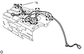
Text in Illustration *A w/ Voltage Inverter Attach the 5 wire harness clamps to install the No. 2 battery pack wire to the upper hybrid battery cover sub-assembly.
-
w/ Voltage Inverter:
Attach the 6 wire harness clamps to install the No. 2 battery pack wire to the upper hybrid battery cover sub-assembly.
-
-
INSTALL UPPER HYBRID BATTERY COVER SUB-ASSEMBLY
CAUTION:
Perform work using insulated gloves and insulated tools.
-
Install the upper hybrid battery cover sub-assembly together with the power steering converter wire with the 11 nuts.
- Torque:
- 7.5 N*m { 76 kgf*cm, 66 in.*lbf }
-
Attach the 3 wire harness clamps to connect the No. 2 hybrid battery pack wire.
-
-
INSTALL REAR NO. 1 HYBRID BATTERY SHIELD
CAUTION:
Perform work using insulated gloves and insulated tools.
-
Install the rear No. 1 hybrid battery shield with the 3 nuts and 2 bolts.
- Torque:
- 7.5 N*m { 76 kgf*cm, 66 in.*lbf }
-
Attach the wire harness clamp and connect the connector.
-
-
INSTALL NO. 2 HYBRID BATTERY INTAKE DUCT
-
Install the No. 2 hybrid battery intake duct with the clip.
-
-
INSTALL BATTERY COOLING BLOWER ASSEMBLY (for Lower Side)
CAUTION:
Perform work using insulated gloves and insulated tools.
-
Install the battery cooling blower assembly with the nut.
- Torque:
- 7.5 N*m { 76 kgf*cm, 66 in.*lbf }
Note
-
Hold the wire harness and fan, and do not install them.
-
Make sure that foreign matter does not enter the battery cooling blower assembly.
-
Connect the connector.
-
Install the 2 nuts.
- Torque:
- 7.5 N*m { 76 kgf*cm, 66 in.*lbf }
-
Attach the wire harness clamp.
-
-
INSTALL VOLTAGE INVERTER ASSEMBLY (w/ Voltage Inverter)
-
INSTALL NO. 1 HV BATTERY SHIELD PANEL
CAUTION:
Perform work using insulated gloves and insulated tools.
-
Install the No. 1 HV battery shield panel with the 4 nuts.
- Torque:
- 8.0 N*m { 82 kgf*cm, 71 in.*lbf }
-
-
INSTALL NO. 3 HYBRID BATTERY INTAKE DUCT
-
Install the No. 3 hybrid battery intake duct to the No. 4 hybrid battery intake duct with the clip.
-
-
INSTALL NO. 2 UPPER HYBRID VEHICLE BATTERY CARRIER BRACKET
-
Install the No. 2 upper hybrid vehicle battery carrier bracket with the bolt.
- Torque:
- 20 N*m { 204 kgf*cm, 15 ft.*lbf }
-
-
INSTALL NO. 1 UPPER HYBRID VEHICLE BATTERY CARRIER BRACKET
-
Install the No. 1 upper hybrid vehicle battery carrier bracket with the bolt.
- Torque:
- 20 N*m { 204 kgf*cm, 15 ft.*lbf }
-
-
INSTALL HV BATTERY
CAUTION:
Be sure to wear insulated gloves.
-
Prepare 2 pieces of cardboard that are at least 540 mm (1.77 ft.) long and 920 mm (3.01 ft.) wide.
-
Place the 2 pieces of cardboard on top of one another in the luggage room.
-
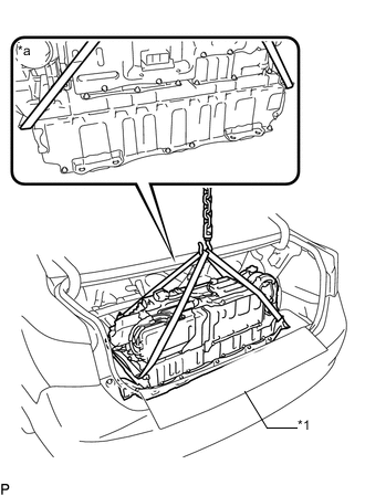
Text in Illustration *1 Top piece of cardboard *a Vehicle Front Using a rope or equivalent, set the HV battery onto the top piece of cardboard.
Note
-
Use cardboard or other similar material to protect the HV battery and vehicle body from damage.
-
Pass the rope or equivalent as shown in the illustration in order to prevent deformation.
-
-
Pull out the rope or equivalent from under the HV battery.
-
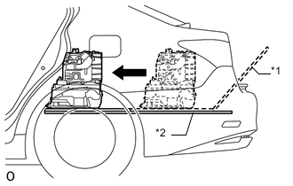
Text in Illustration *1 Top piece of cardboard *2 Bottom piece of cardboard Push the HV battery and top piece of cardboard together into the vehicle, sliding them over the bottom piece of cardboard.
Note
-
When pushing in the HV battery, 2 people are needed. One should work from the luggage compartment side and the other from the cabin side.
-
When pushing in the HV battery, do not allow the wire harnesses and the HV battery case to interfere with the vehicle body.
-
Make sure that the hybrid battery cover sheet attached to the underside of the HV battery does not come off.
-
-
Alternately lifting the left and right sides of the HV battery, pull out both pieces of cardboard from under the HV battery.
-
Temporarily install the 2 nuts for the rear part of the HV battery from the luggage room side.
-
Temporarily install the 4 bolts for the front part of the HV battery from the cabin side.
-
Tighten the 2 nuts for the rear part of the HV battery from the luggage room side.
- Torque:
- 20 N*m { 204 kgf*cm, 15 ft.*lbf }
-
Tighten the 4 bolts for the front part of the HV battery from the cabin room side.
- Torque:
- 20 N*m { 204 kgf*cm, 15 ft.*lbf }
-
Connect the 2 connectors.
-
Connect the connector.
-
-
INSTALL NO. 1 HYBRID BATTERY CARRIER BRACKET
CAUTION:
Be sure to wear insulated gloves.
-
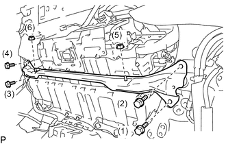
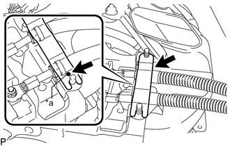
Temporarily install the No. 1 hybrid battery carrier bracket with the 4 bolts and 2 nuts.
-
Tighten the 4 bolts and 2 nuts in the order shown in the illustration.
- Torque:
- Bolt
- 20 N*m { 204 kgf*cm, 15 ft.*lbf }
- Nut
- 20 N*m { 204 kgf*cm, 15 ft.*lbf }
-
-
INSTALL BRAKE CONTROL POWER SUPPLY ASSEMBLY
-
INSTALL NO. 6 HYBRID BATTERY INTAKE DUCT
-
Install the No. 6 hybrid battery intake duct with the 2 clips.
-
-
INSTALL NO. 1 HYBRID BATTERY INTAKE DUCT
-
Install the No. 1 hybrid battery intake duct with the 2 clips.
-
-
CONNECT NO. 4 FLOOR WIRE
CAUTION:
Perform work using insulated gloves and insulated tools.
-
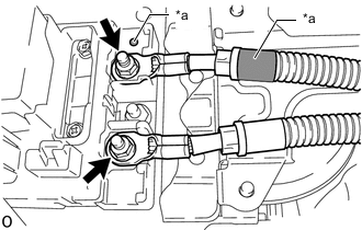
Text in Illustration *a Matchmark Connect the 2 No. 4 floor wires with the 2 nuts.
Note
Be sure to match the red marks on the No. 4 floor wire to the red marks on the hybrid battery junction block assembly and connect the No. 4 floor wire.
- Torque:
- 9.0 N*m { 92 kgf*cm, 80 in.*lbf }
-
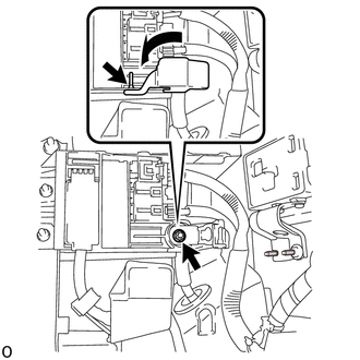
Text in Illustration *a Matchmark Install the battery shield contact.
Note
Align the matchmark when installing the battery shield contact.
-
-
CHECK HIGH VOLTAGE CABLE CONNECTION CONDITION
-
INSTALL NO. 4 HYBRID VEHICLE BATTERY SHIELD SUB-ASSEMBLY
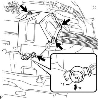
Text in Illustration *1 Button *a Push CAUTION:
Perform work using insulated gloves and insulated tools.
-
Set the No. 4 hybrid vehicle battery shield sub-assembly in place and temporarily install the 4 nuts.
-
Insert the battery cover lock striker and then push the button to lock it.
-
Tighten the 4 nuts.
- Torque:
- 8.0 N*m { 82 kgf*cm, 71 in.*lbf }
-
-
INSTALL INNER LUGGAGE COMPARTMENT TRIM COVER LH
-
INSTALL INNER LUGGAGE COMPARTMENT TRIM COVER RH
-
INSTALL ROPE HOOK
-
INSTALL FRONT LUGGAGE COMPARTMENT TRIM COVER
-
INSTALL REAR FLOOR FINISH PLATE
-
INSTALL REAR LUGGAGE COMPARTMENT TRIM COVER
-
INSTALL NO. 1 LUGGAGE COMPARTMENT LIGHT ASSEMBLY
-
INSTALL NO. 1 LUGGAGE COMPARTMENT TRIM HOOK
-
INSTALL REAR LUGGAGE COMPARTMENT TRAY BRACKET LH
-
INSTALL REAR LUGGAGE COMPARTMENT TRAY BRACKET RH
-
INSTALL ROPE HOOK ASSEMBLY
-
INSTALL LUGGAGE COMPARTMENT SIDE TRAY (w/ Spare Tire)
-
INSTALL SPARE WHEEL COVER TRAY (w/o Spare Tire)
-
INSTALL LUGGAGE COMPARTMENT TRIM BOX (w/o Spare Tire)
-
INSTALL SIDE TRIM BOX
-
INSTALL LUGGAGE COMPARTMENT TRIM COVER RH
-
INSTALL NO. 1 ROOM PARTITION PAD
-
Install the No. 1 room partition pad with the 5 clips.
-
-
INSTALL NO. 2 ROOM PARTITION PAD
-
Install the No. 2 room partition pad with the 2 clips.
-
-
INSTALL NO. 2 PACKAGE TRAY TRIM PANEL ASSEMBLY (w/ Rear Sunshade)
-
INSTALL CENTER STOP LIGHT COVER (w/ Rear Sunshade)
-
INSTALL PACKAGE TRAY TRIM PANEL ASSEMBLY
-
w/o Rear Sunshade:
-
Pass the 3 rear seat belt floor anchors through the package tray trim panel assembly.
-
Insert the package tray trim panel assembly into the 5 guides and attach the 4 clips to install the package tray trim panel assembly.
-
Connect the connector.
-
Attach the 4 claws to install the center stop light cover.
-
-
w/ Rear Sunshade:
-
Pass the 3 rear seat belt floor anchors through the package tray trim panel assembly.
-
Insert the package tray trim panel assembly into the rear window shade assembly and attach the 4 clips to install the package tray trim panel assembly.
-
-
Attach the 4 claws to install the belt guide of rear seat inner with center belt assembly LH to the package tray trim panel assembly.
-
Attach the 4 claws to install the rear seat shoulder belt hole cover to the package tray trim panel assembly.
Tech Tips
Use the same procedure to install the rear seat shoulder belt hole cover on the other side.
-
-
INSTALL INNER ROOF SIDE GARNISH LH
-
INSTALL REAR SEAT SIDE GARNISH LH
-
INSTALL REAR DOOR SCUFF PLATE LH
-
INSTALL INNER ROOF SIDE GARNISH RH
-
INSTALL REAR SEAT SIDE GARNISH RH
-
INSTALL REAR DOOR SCUFF PLATE RH
-
INSTALL REAR SEAT ASSEMBLY
-
INSTALL SERVICE PLUG GRIP
-
INSTALL LOWER HYBRID VEHICLE BATTERY COVER PANEL
-
INSTALL NO. 1 SEAT ARMREST CAP
-
CONNECT CABLE TO AUXILIARY BATTERY TERMINAL
Note
When disconnecting the cable some systems need to be initialized after the cable is reconnected Click here.
-
Connect cable to the auxiliary battery positive (+) terminal with the nut.
- Torque:
- 6.8 N*m { 69 kgf*cm, 60 in.*lbf }
-
Install the terminal cover.
-
Connect cable to the auxiliary battery negative (-) terminal.
- Torque:
- 5.5 N*m { 56 kgf*cm, 49 in.*lbf }
-
-
INSTALL LUGGAGE COMPARTMENT TRIM COVER LH
-
INSTALL LUGGAGE COMPARTMENT FLOOR MAT