INVERTER WITH CONVERTER INSTALLATION
PROCEDURE
-
INSTALL HIGH VOLTAGE FUSE
CAUTION:
Wear insulated gloves.
Tech Tips
Perform this procedure only when replacement of the high voltage fuse is necessary.
-
Remove the bolt and connector cover assembly.
Note
-
Make sure to pull the connector cover assembly straight up, as a connector is connected to the bottom of the cover.
-
Do not allow any foreign objects or water to enter the inverter with converter assembly.
-
-
Install the high voltage fuse with 2 new nuts.
- Torque:
- 4.0 N*m { 41 kgf*cm, 35 in.*lbf }
Note
Be sure to use a torque wrench to tighten the nuts.
-
Temporarily install the connector cover assembly with the bolt to prevent any foreign objects or water from entering the inverter with converter assembly.
-
-
INSTALL INVERTER BUS-BAR PLATE SUB-ASSEMBLY
-
Temporarily install the inverter bus-bar plate sub-assembly with the nut by tightening the nut 3 or more revolutions.
-
Install the bolt and attach the clamp.
- Torque:
- 8.0 N*m { 82 kgf*cm, 71 in.*lbf }
-
Tighten the nut.
- Torque:
- 18 N*m { 184 kgf*cm, 13 ft.*lbf }
-
Close the cover.
-
-
INSTALL NO. 4 INVERTER BRACKET
-
Install the No. 4 inverter bracket with the 2 bolts.
- Torque:
- 8.0 N*m { 82 kgf*cm, 71 in.*lbf }
-
for RHD:
Install the wire harness bracket with the bolt.
- Torque:
- 10 N*m { 102 kgf*cm, 7 ft.*lbf }
-
-
INSTALL INVERTER WITH CONVERTER ASSEMBLY
CAUTION:
Wear insulated gloves.
-
Temporarily install the No. 6 inverter bracket and inverter with converter assembly with the 6 bolts.
Note
-
Since the inverter with converter assembly is very heavy, 2 people are needed to install the inverter with converter assembly. When installing the inverter with converter assembly, do not damage the parts around it.
-
To prevent damage, do not hold the inverter with converter assembly by the connectors.
-
To prevent damage due to static electricity, do not touch the terminals of the disconnected connectors.
-
-
Remove the bolt and connector cover assembly.
Note
-
Make sure to pull the connector cover assembly straight up, as a connector is connected to the bottom of the connector cover assembly.
-
Do not allow any foreign objects or water to enter the inverter with converter assembly.
-
-
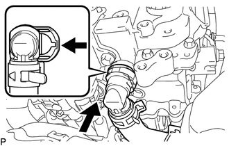
Connect the No. 4 floor wire to the inverter with converter assembly.
Note
-
Do not damage the terminals, connector housings or inverter with converter assembly when connecting them.
-
Do not touch the connector waterproofing rubber or terminals.
-
Do not allow any foreign objects or water to enter the inverter with converter assembly.
-
Make sure that the connectors are fully engaged.
-
Make sure that the connector does not come out when its body is pulled.
-
-
Secure the No. 4 floor wire to the inverter with converter assembly with the bolt.
- Torque:
- 8.0 N*m { 82 kgf*cm, 71 in.*lbf }
-
Connect the air conditioning harness to the inverter with converter assembly.
Note
-
Do not damage the terminals, connector housings or inverter with converter assembly when connecting them.
-
Do not touch the connector waterproofing rubber or terminals.
-
Do not allow any foreign objects or water to enter the inverter with converter assembly.
-
Make sure that the connectors are fully engaged.
-
Make sure that the connector does not come out when its body is pulled.
-
-
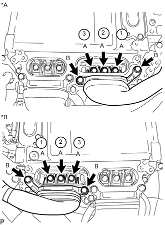
Tighten the 6 bolts in the order shown in the illustration.
- Torque:
- 8.0 N*m { 82 kgf*cm, 71 in.*lbf }
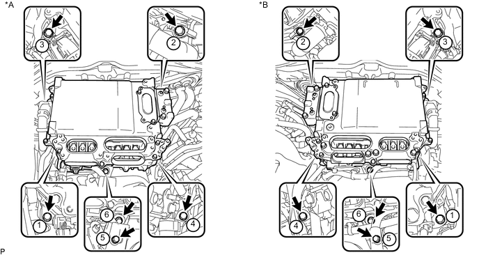
Text in Illustration *A for LHD *B for RHD -
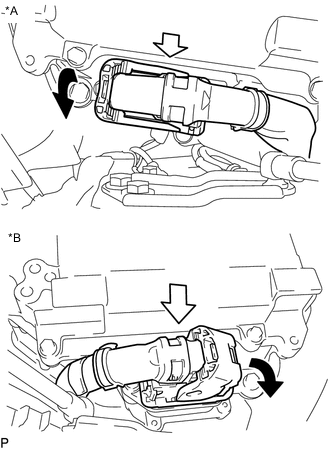
Text in Illustration *A for LHD *B for RHD Connect the connector and lock the connector with the lock lever.
Note
-
Do not allow any foreign objects or water to enter the inverter with converter assembly.
-
Make sure that the connectors are fully engaged.
-
-
-
CONNECT INVERTER BUS-BAR PLATE SUB-ASSEMBLY
-
for LHD:
-
Install the wire harness bracket with the bolt.
- Torque:
- 8.5 N*m { 87 kgf*cm, 75 in.*lbf }
-
Temporarily install the inverter bus-bar plate sub-assembly with the 3 nuts.
-
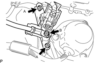
Tighten the 2 nuts labeled A in the illustration.
- Torque:
- 6.9 N*m { 70 kgf*cm, 61 in.*lbf }
-
Tighten the nut labeled B in the illustration.
- Torque:
- 11 N*m { 107 kgf*cm, 8 ft.*lbf }
-
Attach the harness cover.
-
-
for RHD:
-
Attach the 2 claws and install the nut.
- Torque:
- 11 N*m { 107 kgf*cm, 8 ft.*lbf }
-
Install the relay block cover.
-
Connect the connector and attach the clamp.
-
-
-
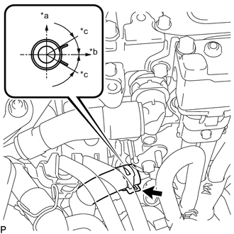
CONNECT NO. 2 INVERTER COOLING INLET HOSE (for RHD)
-
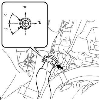
Text in Illustration *a Upper *b LH Side *c 30° Connect the No. 2 inverter cooling inlet hose to the inverter with converter assembly, and slide the clamp to secure the hose.
Note
To prevent foreign matter from entering the cooling system, do not remove the pieces of cloth or plastic bags from the pipes and disconnected hoses.
Tech Tips
Make sure the direction of the hose clamp is as shown in the illustration.
-
-
CONNECT NO. 1 INVERTER COOLING INLET HOSE (for LHD)
-
Text in Illustration *a Upper *b LH Side *c 30° Connect the No. 1 inverter cooling inlet hose to the inverter with converter assembly, and slide the clamp to secure the hose.
Note
To prevent foreign matter from entering the cooling system, do not remove the pieces of cloth or plastic bags from the pipes and disconnected hoses.
Tech Tips
Make sure the direction of the hose clamp is as shown in the illustration.
-
-
INSTALL INVERTER INLET PIPE ASSEMBLY (for RHD)
-
Install the inverter inlet pipe assembly with the bolt and nut to the suspension tower LH.
- Torque:
- 13 N*m { 127 kgf*cm, 9 ft.*lbf }
-
Connect the No. 2 inverter cooling outlet hose to the inverter with converter assembly and lock the hose with the retainer.
Note
-
Insert the retainer until a click sound is heard.
-
Pull on the hose to confirm that the hose is securely connected.
-
If there is foreign matter on the union or the O-ring, clean it with water and finger scouring.
-
To prevent foreign matter from entering the cooling system, do not remove the pieces of cloth or plastic bags from the pipes and disconnected hoses.
-
-
-
INSTALL NO. 1 INVERTER COOLING OUTLET HOSE (for LHD)
-
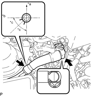
Text in Illustration *a Upper *b RH Side *c 44.5° Install the No. 1 inverter cooling outlet hose to the inverter with converter assembly, lock the hose with the retainer and slide the clamp to secure the hose.
Note
-
Insert the retainer until a click sound is heard.
-
Pull on the hose to confirm that the hose is securely connected.
-
If there is foreign matter on the union or the O-ring, clean it with water and finger scouring.
-
To prevent foreign matter from entering the cooling system, do not remove the pieces of cloth or plastic bags from the pipes and disconnected hoses.
-
-
-
CONNECT FUEL TUBE SUB-ASSEMBLY (for LHD)
-
INSTALL CONNECTOR COVER ASSEMBLY
CAUTION:
Wear insulated gloves.
Note
-
Make sure that the interlock is fully engaged.
-
Do not allow any foreign objects or water to enter the inverter with converter assembly.
-
Using an insulated tool, install the connector cover assembly with the 2 bolts.
- Torque:
- 8.0 N*m { 82 kgf*cm, 71 in.*lbf }
-
-
CONNECT MOTOR CABLE
CAUTION:
Wear insulated gloves.
Note
-
Do not damage the terminals, connector housings or inverter with converter assembly when connecting them.
-
Do not touch the connector waterproofing rubber or terminals.
-
Do not allow any foreign objects or water to enter the inverter with converter assembly.
-
Temporarily install the motor cable with the 5 bolts.
-
Text in Illustration *A for LHD *B for RHD Using an insulated tool, tighten the 3 bolts labeled A in the illustration.
- Torque:
- 8.0 N*m { 82 kgf*cm, 71 in.*lbf }
Note
-
The connector should be connected securely.
-
The bolts should be tightened securely.
-
Tighten the bolts in the order shown in the illustration.
-
Using an insulated tool, tighten the 2 bolts labeled B in the illustration.
- Torque:
- 8.0 N*m { 82 kgf*cm, 71 in.*lbf }
Note
-
The connector should be connected securely.
-
The bolts should be tightened securely.
-
-
CONNECT GENERATOR CABLE
CAUTION:
Wear insulated gloves.
Note
-
Do not damage the terminals, connector housings or inverter with converter assembly when connecting them.
-
Do not touch the connector waterproofing rubber or terminals.
-
Do not allow any foreign objects or water to enter the inverter with converter assembly.
-
Temporarily install the generator cable with the 5 bolts.
-
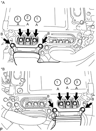
Text in Illustration *A for LHD *B for RHD Using an insulated tool, tighten the 3 bolts labeled A in the illustration.
- Torque:
- 8.0 N*m { 82 kgf*cm, 71 in.*lbf }
Note
-
The connector should be connected securely.
-
The bolts should be tightened securely.
-
Tighten the bolts in the order shown in the illustration.
-
Using an insulated tool, tighten the 2 bolts labeled B in the illustration.
- Torque:
- 8.0 N*m { 82 kgf*cm, 71 in.*lbf }
Note
-
The connector should be connected securely.
-
The bolts should be tightened securely.
-
-
INSTALL INVERTER TERMINAL COVER
CAUTION:
Wear insulated gloves.
-
for Type A:
-
Using an insulated tool, install the inverter terminal cover with the 2 bolts.
- Torque:
- 8.0 N*m { 82 kgf*cm, 71 in.*lbf }
Note
-
Do not touch the inverter terminal cover waterproofing rubber.
-
Visually confirm that the inverter terminal cover waterproofing rubber is securely installed before installing the inverter terminal cover.
-
Press down on the inverter terminal cover with both hands to securely connect the interlock.
-
-
for Type B:
-
Using an insulated tool, install the inverter terminal cover with the 3 bolts.
- Torque:
- 8.0 N*m { 82 kgf*cm, 71 in.*lbf }
Note
-
Do not touch the inverter terminal cover waterproofing rubber.
-
Visually confirm that the inverter terminal cover waterproofing rubber is securely installed before installing the inverter terminal cover.
-
Press down on the inverter terminal cover with both hands to securely connect the interlock.
-
-
-
INSTALL INVERTER MOTOR CABLE BRACKET ASSEMBLY
-
Install the inverter motor cable bracket assembly with the 2 bolts.
- Torque:
- 8.0 N*m { 82 kgf*cm, 71 in.*lbf }
-
Attach the 2 clamps to the inverter motor cable bracket assembly.
-
-
INSTALL AIR CLEANER HOSE ASSEMBLY (for LHD)
-
INSTALL AIR CLEANER CAP WITH NO. 2 AIR CLEANER HOSE (for LHD)
-
INSTALL SERVICE PLUG GRIP
-
CONNECT CABLE TO AUXILIARY NEGATIVE BATTERY TERMINAL
-
CONNECT INVERTER COOLING HOSE ASSEMBLY (for RHD)
-
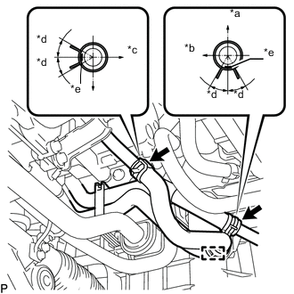
Text in Illustration *a Upper *b Front Side *c LH Side *d 30° *e Paint Mark Connect the 2 ends of the inverter cooling hoses to the inverter cooling pipes and secure the hoses with the 2 hose clamps.
Tech Tips
Make sure that the clamps are positioned as shown in the illustration.
-
Attach the inverter cooling hose clamp to the inverter cooling pipe assembly.
-
-
ADD COOLANT (for Inverter)
-
INSPECT FOR COOLANT LEAK (for Inverter)
-
INSTALL NO. 1 ENGINE COVER SUB-ASSEMBLY
-
INSTALL INVERTER COVER
-
Attach the 2 inverter cover claws to the inverter with converter. Then attach the inverter cover with the clip.
-
-
INSTALL ENGINE UNDER COVER
-
INSTALL NO. 1 AIR CLEANER INLET
-
INSTALL COOL AIR INTAKE DUCT SEAL
-
INSTALL ENGINE ROOM SIDE COVER
-
INSTALL LUGGAGE COMPARTMENT TRIM COVER LH
-
INSTALL LUGGAGE COMPARTMENT FLOOR MAT