LIGHTING SYSTEM Power Source Circuit
DESCRIPTION
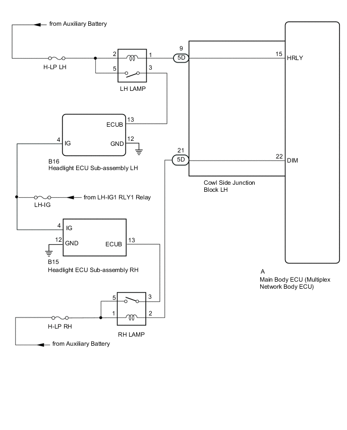
The main body ECU (multiplex network body ECU) receives IG signals and supplies power to the headlight ECU sub-assembly via the headlight light dimmer relay.
WIRING DIAGRAM
CAUTION / NOTICE / HINT
Note
-
Inspect the fuses for circuits related to this system before performing the following inspection procedure.
-
Recognition code registration is necessary when replacing the main body ECU (multiplex network body ECU).
-
If the main body ECU (multiplex network body ECU) is replaced, refer to Service Bulletin.
PROCEDURE
-
CHECK HARNESS AND CONNECTOR (HEADLIGHT ECU SUB-ASSEMBLY - POWER SOURCE AND BODY GROUND)
-
Disconnect the B16*1and B15*2 headlight ECU sub-assembly connectors.
-
*1: for LH Side
-
*2: for RH Side
-
-
Measure the voltage according to the value(s) in the table below.
Standard Voltage for LH Side Tester Connection Switch Condition Specified Condition B16-13 (ECUB) - Body ground Power switch on (IG) 11 to 14 V B16-4 (IG) - Body ground Power switch on (IG) 11 to 14 V for RH Side Tester Connection Switch Condition Specified Condition B15-13 (ECUB) - Body ground Power switch on (IG) 11 to 14 V B15-4 (IG) - Body ground Power switch on (IG) 11 to 14 V -
Measure the resistance according to the value(s) in the table below.
Standard Resistance for LH Side Tester Connection Condition Specified Condition B16-12 (GND) - Body ground Always Below 1 Ω for RH Side Tester Connection Condition Specified Condition B15-12 (GND) - Body ground Always Below 1 Ω Result Result Proceed to OK A NG (for LH Side) B NG (for RH Side) C
A 
PROCEED TO NEXT SUSPECTED AREA SHOWN IN PROBLEM SYMPTOMS TABLE Click here
C 
CHECK HARNESS AND CONNECTOR (BATTERY - RH LAMP RELAY) Click here
B 
-
-
CHECK HARNESS AND CONNECTOR (BATTERY - LH LAMP RELAY)
-
Remove the LH LAMP relay relay from the No. 2 engine room relay block.
-
Measure the voltage according to the value(s) in the table below.
Standard Voltage Tester Connection Switch Condition Specified Condition Relay terminal 2 - Body ground Power switch off 11 to 14 V Relay terminal 5 - Body ground Power switch off 11 to 14 V
NG
REPAIR OR REPLACE HARNESS OR CONNECTOR
OK
-
-
INSPECT LH LAMP RELAY
-
Remove the LH LAMP relay from the No. 2 engine room relay block.
-
Inspect the LH LAMP relay Click here.
NG
REPLACE LH LAMP RELAY
OK
-
-
CHECK HARNESS AND CONNECTOR (LH LAMP RELAY - HEADLIGHT ECU SUB-ASSEMBLY LH)
-
Remove the LH LAMP relay from the No. 2 engine room relay block.
-
Disconnect the B16 headlight ECU sub-assembly LH connectors.
-
Measure the resistance according to the value(s) in the table below.
Standard Resistance Tester Connection Condition Specified Condition Relay terminal 3 - B16-13 (ECUB) Always Below 1 Ω Relay terminal 3 or B16-13 (ECUB) - Body ground Always 10 kΩ or higher
NG
REPAIR OR REPLACE HARNESS OR CONNECTOR
OK
-
-
CHECK HARNESS AND CONNECTOR (LH LAMP RELAY - COWL SIDE JUNCTION BLOCK LH)
-
Remove the LH LAMP relay from the No. 2 engine room relay block.
-
Disconnect the 5D cowl side junction block connector.
-
Measure the resistance according to the value(s) in the table below.
Standard Resistance Tester Connection Condition Specified Condition Relay terminal 1 - 5D-9 Always Below 1 Ω Relay terminal 1 or 5D-9 - Body ground Always 10 kΩ or higher
NG
REPAIR OR REPLACE HARNESS OR CONNECTOR
OK
-
-
INSPECT COWL SIDE JUNCTION BLOCK LH
-
Remove the cowl side junction block LH Click here.
-
Remove the main body ECU from the cowl side junction block LH Click here.
-
Measure the resistance according to the value(s) in the table below.
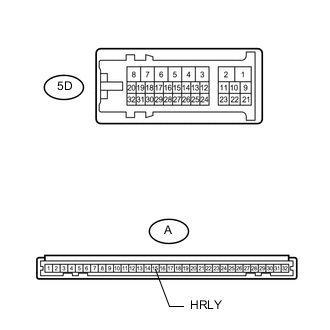
Standard Resistance Tester Connection Condition Specified Condition 5D-9 - A-15 (HRLY) Always Below 1 Ω
OK
REPLACE MAIN BODY ECU (MULTIPLEX NETWORK BODY ECU) Click here
NG
REPLACE COWL SIDE JUNCTION BLOCK LH Click here
-
-
CHECK HARNESS AND CONNECTOR (BATTERY - RH LAMP RELAY)
-
Remove the RH LAMP relay from the No. 2 engine room relay block.
-
Measure the voltage according to the value(s) in the table below.
Standard Voltage Tester Connection Switch Condition Specified Condition Relay terminal 1 - Body ground Power switch off 11 to 14 V Relay terminal 5 - Body ground Power switch off 11 to 14 V
NG
REPAIR OR REPLACE HARNESS OR CONNECTOR
OK
-
-
INSPECT RH LAMP RELAY
-
Remove the RH LAMP relay from the No. 2 engine room relay block.
-
Inspect the RH LAMP relay Click here.
NG
REPLACE RH LAMP RELAY
OK
-
-
CHECK HARNESS AND CONNECTOR (RH LAMP RELAY - HEADLIGHT ECU SUB-ASSEMBLY RH)
-
Remove the RH LAMP relay from the No. 2 engine room relay block.
-
Disconnect the B15 headlight ECU sub-assembly RH connectors.
-
Measure the resistance according to the value(s) in the table below.
Standard Resistance Tester Connection Condition Specified Condition Relay terminal 3 - B15-13 (ECUB) Always Below 1 Ω Relay terminal 3 or B15-13 (ECUB) - Body ground Always 10 kΩ or higher
NG
REPAIR OR REPLACE HARNESS OR CONNECTOR
OK
-
-
CHECK HARNESS AND CONNECTOR (RH LAMP RELAY - COWL SIDE JUNCTION BLOCK LH)
-
Remove the RH LAMP relay from the No. 2 engine room relay block.
-
Disconnect the 5D cowl side junction block LH connector.
-
Measure the resistance according to the value(s) in the table below.
Standard Resistance Tester Connection Condition Specified Condition Relay terminal 2 - 5D-21 Always Below 1 Ω Relay terminal 2 or 5D-21 - Body ground Always 10 kΩ or higher
NG
REPAIR OR REPLACE HARNESS OR CONNECTOR
OK
-
-
INSPECT COWL SIDE JUNCTION BLOCK LH
-
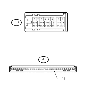
*1 DIM Remove the cowl side junction block LH Click here.
-
Remove the main body ECU from the cowl side junction block LH Click here.
-
Measure the resistance according to the value(s) in the table below.
Standard Resistance Tester Connection Condition Specified Condition 5D-21 - A-22 (DIM) Always Below 1 Ω
OK
REPLACE MAIN BODY ECU (MULTIPLEX NETWORK BODY ECU) Click here
NG
REPLACE COWL SIDE JUNCTION BLOCK LH Click here
-