LIGHTING SYSTEM Taillight Relay Circuit
DESCRIPTION
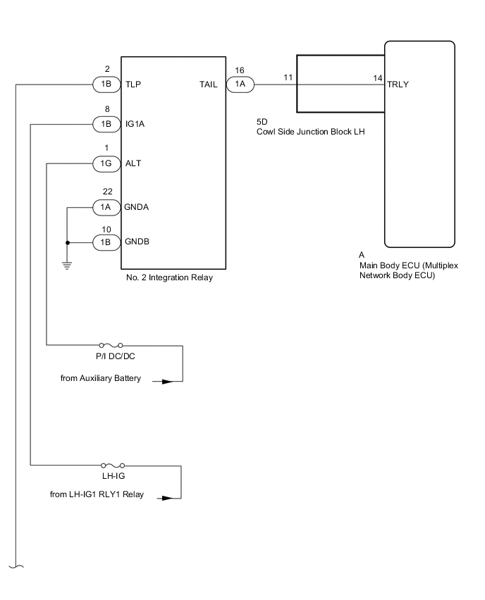
The main body ECU (multiplex network body ECU) controls the operation of the TAIL relay.
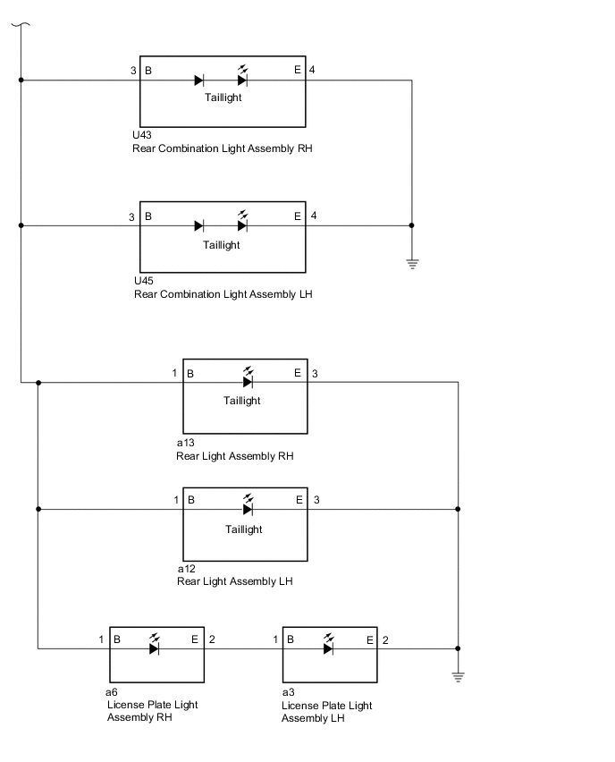
WIRING DIAGRAM
CAUTION / NOTICE / HINT
Note
-
Inspect the fuses for circuits related to this system before performing the following inspection procedure.
-
Recognition code registration is necessary when replacing the main body ECU (multiplex network body ECU).
-
Before replacing the main body ECU (multiplex network body ECU), refer to Registration.
PROCEDURE
-
PERFORM ACTIVE TEST USING GTS (TAILLIGHT RELAY)
-
Using the GTS, perform the Active Test Click here.
Main Body Tester Display Test Part Control Range Diagnostic Note Taillight Relay Taillight relay ON/OFF - OK Taillights come on.
OK 
PROCEED TO NEXT SUSPECTED AREA SHOWN IN PROBLEM SYMPTOMS TABLE Click here
NG 
-
-
CHECK HARNESS AND CONNECTOR (NO. 2 INTEGRATION RELAY - BATTERY AND BODY GROUND)
-
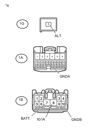
Text in Illustration *a Front view of wire harness connector
(to No. 2 Integration Relay)
Disconnect the No. 2 integration relay connectors.
-
Measure the voltage according to the value(s) in the table below.
Standard Voltage Tester Connection Switch Condition Specified Condition 1G-1 (ALT) - Body ground Power switch off 11 to 14 V 1B-7 (BATT) - Body ground Power switch off 11 to 14 V 1B-8 (IG1A) - Body ground Power switch on (IG) 11 to 14 V -
Measure the resistance according to the value(s) in the table below.
Standard Resistance Tester Connection Condition Specified Condition 1B-10 (GNDB) - Body ground Always Below 1 Ω 1A-22 (GNDA) - Body ground Always Below 1 Ω
NG
REPAIR OR REPLACE HARNESS OR CONNECTOR
OK
-
-
CHECK HARNESS AND CONNECTOR (NO. 2 INTEGRATION RELAY - REAR COMBINATION LIGHT ASSEMBLY)
-
Disconnect the 1B No. 2 integration relay connector.
-
Disconnect the U43 rear combination light assembly RH connector.
-
Measure the resistance according to the value(s) in the table below.
Standard Resistance Tester Connection Condition S5Dcified Condition 1B-2 (TLP) - U43-3 (B) Always Below 1 Ω
NG
REPAIR OR REPLACE HARNESS OR CONNECTOR
OK
-
-
CHECK HARNESS AND CONNECTOR (NO. 2 INTEGRATION RELAY - COWL SIDE JUNCTION BLOCK LH)
-
Disconnect the 1A No. 2 integration relay connector.
-
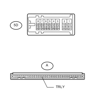
Disconnect the 5D cowl side junction block LH connector.
-
Measure the resistance according to the value(s) in the table below.
Standard Resistance Tester Connection Condition S5Dcified Condition 1A-16 (TAIL) - 5D-11 Always Below 1 Ω 1A-16 (TAIL) - Body ground Always 10 kΩ or higher
NG
REPAIR OR REPLACE HARNESS OR CONNECTOR
OK
-
-
INSPECT COWL SIDE JUNCTION BLOCK LH
-
Remove the cowl side junction block LH Click here.
-
Remove the main body ECU from the cowl side junction block LH Click here.
-
Measure the resistance according to the value(s) in the table below.
Standard Resistance Tester Connection Condition S5Dcified Condition A-14 (TRLY) - 5D-11 Always Below 1 Ω
OK
REPLACE MAIN BODY ECU (MULTIPLEX NETWORK BODY ECU) Click here
NG
REPLACE COWL SIDE JUNCTION BLOCK LH Click here
-