LIGHTING SYSTEM Rear Fog Light Circuit
DESCRIPTION
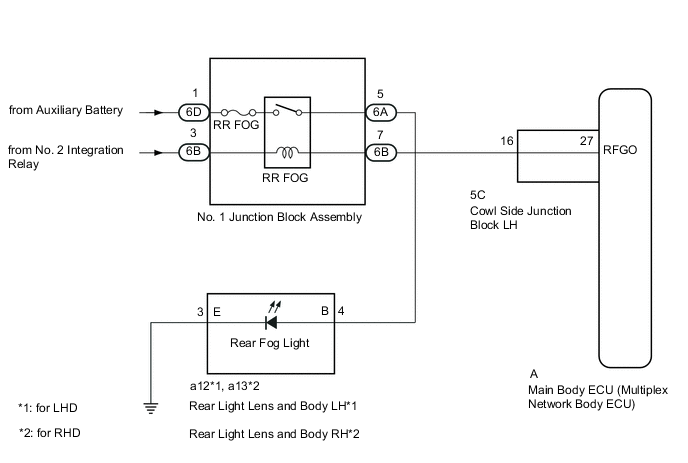
The main body ECU receives headlight dimmer switch information signals and illuminates the rear fog lights.
WIRING DIAGRAM
CAUTION / NOTICE / HINT
Note
-
Inspect the fuses for circuits related to this system before performing the following inspection procedure.
-
Recognition code registration is necessary when replacing the main body ECU (multiplex network body ECU).
-
If the main body ECU (multiplex network body ECU) is replaced, refer to the Service Bulletin.
PROCEDURE
-
PERFORM ACTIVE TEST USING GTS (REAR FOG LIGHT RELAY)
-
Using the GTS, perform the Active Test Click here.
Main Body Tester Display Test Part Control Range Diagnostic Note Rear Fog Light Relay Rear fog light relay ON/OFF The headlight dimmer switch is in the tail position. OK Rear fog light relay operates (rear fog lights come on).
OK 
PROCEED TO NEXT SUSPECTED AREA SHOWN IN PROBLEM SYMPTOMS TABLE Click here
NG 
-
-
CHECK HARNESS AND CONNECTOR (NO. 1 JUNCTION BLOCK - BATTERY)
-
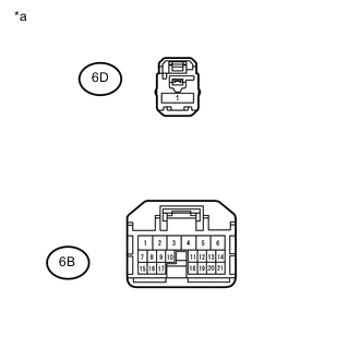
Text in Illustration *a Front view of wire harness connector
(to No. 1 Junction Block Assembly)
Disconnect the No. 1 junction block connector.
-
Measure the voltage according to the value(s) in the table below.
Standard Voltage Tester Connection Condition Specified Condition 6D-1 - Body ground Power switch off 11 to 14 V 6B-3 - Body ground Headlight dimmer switch in tail 11 to 14 V
NG
REPAIR OR REPLACE HARNESS OR CONNECTOR
OK
-
-
INSPECT NO. 1 JUNCTION BLOCK ASSEMBLY
-
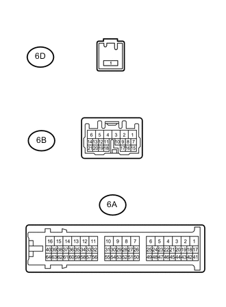
Remove the No. 1 junction block.
-
Measure the resistance according to the value(s) in the table below.
Standard Resistance Tester Connection Condition Specified Condition 6D-1 - 6A-5 Auxiliary battery voltage applied between terminals 6B-3 and 6B-7 Below 1 Ω Auxiliary battery voltage not applied between terminals 6B-3 and 6B-7 10 kΩ or higher
NG
REPLACE NO. 1 JUNCTION BLOCK ASSEMBLY
OK
-
-
CHECK HARNESS AND CONNECTOR (NO. 1 JUNCTION BLOCK - COWL SIDE JUNCTION BLOCK LH)
-
Disconnect the 6B No. 1 junction block connector.
-
Disconnect the 5C cowl side junction block LH connector.
-
Measure the resistance according to the value(s) in the table below.
Standard Resistance Tester Connection Condition Specified Condition 6B-7 - 5C-16 Always Below 1 Ω 6B-7 - Body ground Always 10 kΩ or higher
NG
REPAIR OR REPLACE HARNESS OR CONNECTOR
OK
-
-
INSPECT COWL SIDE JUNCTION BLOCK LH
-
Remove the cowl side junction block LH Click here.
-
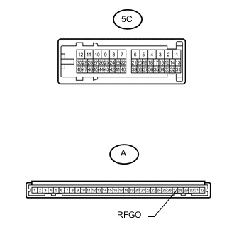
Remove the main body ECU from the cowl side junction block LH Click here.
-
Measure the resistance according to the value(s) in the table below.
Standard Resistance Tester Connection Condition Specified Condition A-27 (RFGO) - 5C-16 Always Below 1 Ω
OK
REPLACE MAIN BODY ECU (MULTIPLEX NETWORK BODY ECU) Click here
NG
REPLACE COWL SIDE JUNCTION BLOCK LH Click here
-