LUGGAGE COMPARTMENT DOOR CLOSER SYSTEM TERMINALS OF ECU
-
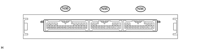
CHECK CERTIFICATION ECU (SMART KEY ECU ASSEMBLY)
-
Disconnect the N94 and N95 certification ECU (smart key ECU assembly) connectors.
-
Measure the resistance and voltage according to the value(s) in the table below.
Terminal No. (Symbol) Wiring Color Terminal Description Condition Specified Condition N95-5 (+B) - Body ground W - Body ground Battery power supply Power switch off 11 to 14 V N95-16 (IG) - Body ground G - Body ground Ignition power supply Power switch off Below 1 V Power switch on (IG) 11 to 14 V N95-4 (CUTB) - Body ground P - Body ground Dark current cut fuse pin input signal Power switch off 11 to 14 V N94-1 (E) - Body ground W-B - Body ground Ground Always Below 1 Ω -
Reconnect the N94 and N95 certification ECU (smart key ECU assembly) connectors.
-
Measure the voltage according to the value(s) in the table below.
Terminal No. (Symbol) Wiring Color Terminal Description Condition Specified Condition N98-22 (TSW5) - N94-1 (E) SB - W-B Luggage electrical key switch input signal Luggage electrical key switch off Below 1 V N98-22 (TSW5) - N94-1 (E) SB - W-B Luggage electrical key switch input signal Power switch on (IG), luggage compartment door is fully closed and luggage electrical key switch off Pulse generation
-
-
CHECK COWL SIDE JUNCTION BLOCK LH AND MAIN BODY ECU (MULTIPLEX NETWORK BODY ECU)
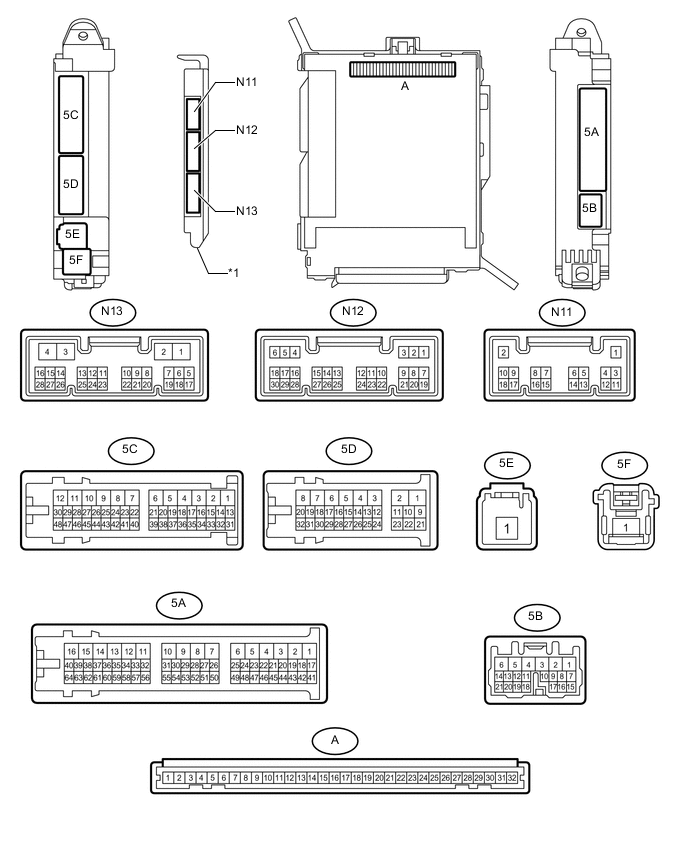
Text in Illustration *1 Main Body ECU (Multiplex Network Body ECU) - -
-
Remove the main body ECU (multiplex network body ECU) from the cowl side junction block LH Click here.
-
Connect the cowl side junction block LH connectors.
-
Measure the voltage and resistance according to the value(s) in the table below.
Terminal No. (Symbol) Wiring Color Terminal Description Condition Specified Condition A-11 (GND1) - Body ground None - Body ground Ground Always Below 1 Ω A-29 (ACC) - Body ground None - Body ground ACC power supply Power switch on (ACC) 11 to 14 V Power switch off Below 1 V A-30 (BECU) - Body ground None - Body ground Auxiliary battery power supply Power switch off 11 to 14 V A-31 (ALTB) - Body ground None - Body ground Auxiliary battery power supply Power switch off 11 to 14 V A-32 (IG) - Body ground None - Body ground IG power supply Power switch on (IG) 11 to 14 V Power switch off Below 1 V -
Install the main body ECU (multiplex network body ECU) to the cowl side junction block LH Click here.
-
Measure the voltage according to the value(s) in the table below.
Terminal No. (Symbol) Wiring Color Terminal Description Condition Specified Condition N13-5 (TMSW) - Body ground G - Body ground Luggage door opening cancel switch input signal Luggage door opening cancel switch is on Below 1 V Power switch off, all doors closed and luggage door opening cancel switch is off Pulse generation N13-8 (TSW) - Body ground Y - Body ground Luggage door opening switch input signal Luggage door opening switch is on Below 1 V Power switch off, all doors closed and luggage door opening switch is off Pulse generation N12-23 (TKUL) - Body ground GR - Body ground Luggage compartment door lock cylinder input signal Power switch off, luggage compartment door lock cylinder operated Below 1 V Power switch off, luggage compartment door lock cylinder not operated Pulse generation
-
-
CHECK MULTIPLEX NETWORK DOOR ECU (w/o Power Trunk Lid System)

-
Disconnect the U68 multiplex network door ECU connector.
-
Measure the resistance and voltage according to the value(s) in the table below.
Terminal No. (Symbol) Wiring Color Terminal Description Condition Specified Condition U68-16 (IG) - U68-1 (GND) B - W-B IG power supply Power switch on (IG) 11 to 14 V U68-18 (ECUB) - U68-1 (GND) P- W-B ECU power supply Power switch off 11 to 14 V U68-1 (GND) - Body ground W-B - Body ground Ground Always Below 1 Ω U68-19 (B) - U68-1 (GND) L - W-B Auxiliary battery power supply Power switch off 11 to 14 V -
Reconnect the U68 motor connector.
-
Measure the voltage according to the value(s) in the table below.
Terminal No. (Symbol) Wiring Color Terminal Description Condition Specified Condition U68-6 (LCM+) - U68-1 (GND) Y - W-B Luggage compartment door closer motor output signal Luggage compartment door closer is operated 11 to 14 V U68-7 (LCM-) - U68-1 (GND) G - W-B Luggage compartment door closer motor output signal Luggage compartment door closer is operated in reverse 11 to 14 V U68-13 (HAF) - U68-1 (GND) W - W-B Luggage compartment door closer half latch switch input signal Power switch on (IG), luggage compartment door open → fully closed Below 1 V → Pulse generation U68-14 (PAWL) - U68-1 (GND) L - W-B Luggage compartment door closer pawl switch input signal Power switch on (IG), luggage compartment door open → fully closed Below 1 V → Pulse generation
-
-
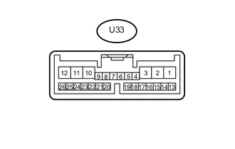
CHECK LUGGAGE CLOSER MOTOR ASSEMBLY (w/ Power Trunk Lid System)
-
Disconnect the U33 luggage closer motor assembly connector.
-
Measure the resistance and voltage according to the value(s) in the table below.
Terminal No. (Symbol) Wiring Color Terminal Description Condition Specified Condition U33-8 (IG) - U33-11 (GND) B - W-B IG power supply Power switch on (IG) 11 to 14 V U33-10 (ECUB) - U33-11 (GND) P - W-B ECU power supply Power switch off 11 to 14 V U33-11 (GND) - Body ground W-B - Body ground Ground Always Below 1 Ω U33-12 (B) - U33-11 (GND) L - W-B Auxiliary battery power supply Power switch off 11 to 14 V -
Reconnect the U33 motor connector.
-
Measure the voltage according to the value(s) in the table below.
Terminal No. (Symbol) Wiring Color Terminal Description Condition Specified Condition U33-2 (LCM+) - U33-11 (GND) Y - W-B Luggage compartment door closer motor output signal Luggage compartment door closer is operated 11 to 14 V U33-1 (LCM-) - U33-11 (GND) G - W-B Luggage compartment door closer motor output signal Luggage compartment door closer is operated in reverse 11 to 14 V U33-7 (HAF) - U33-11 (GND) W - W-B Luggage compartment door closer half latch switch input signal Power switch on (IG), luggage compartment door open → fully closed Below 1 V → Pulse generation U33-20 (PAWL) - U33-11 (GND) L - W-B Luggage compartment door closer pawl switch input signal Power switch on (IG), luggage compartment door open → fully closed Below 1 V → Pulse generation
-