SLIDING ROOF HOUSING INSTALLATION
PROCEDURE
-
INSTALL SLIDING ROOF HOUSING SUB-ASSEMBLY
-
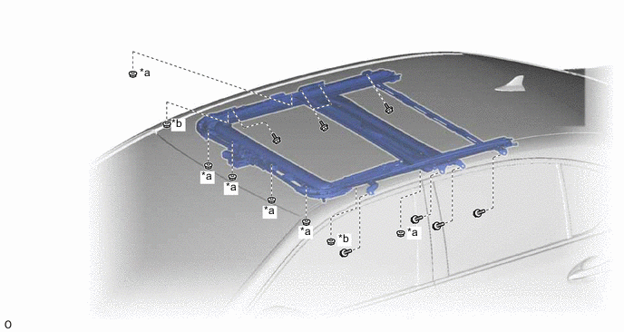
Install the sliding roof housing sub-assembly with the 8 bolts, new 6 nuts (Nut A), and new 2 nuts (Nut B).
Note
Use the specified torque to tighten the nuts. If excessive torque is applied, the studs will be broken.
- Torque:
- Nut A
- 5.5 N*m { 56 kgf*cm, 49 in.*lbf }
- Nut B
- 10 N*m { 102 kgf*cm, 7 ft.*lbf }
- Bolt
- 8.0 N*m { 82 kgf*cm, 71 in.*lbf }
Text in Illustration *a Nut A *b Nut B -
Tighten the bolt of each sliding roof housing front mounting bracket.
- Torque:
- 8.0 N*m { 82 kgf*cm, 71 in.*lbf }
-
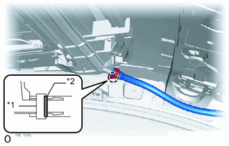
Text in Illustration *1 Clamp *2 Marking for Clamp Type:
-
Insert the sliding roof drain hose.
Tech Tips
The hose should be inserted to the base of the drain pipe.
-
Attach the claw to connect the sliding roof drain hose.
Tech Tips
-
Make sure that the clamp is on the marking or between the marking and hose end.
-
Use the same procedure for the other 3 sliding roof drain hoses.
-
-
-
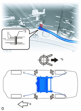
Text in Illustration *1 Clip *2 Marking *a Front Side *b Outside for Clip Type:
-
Expand the clip to insert the sliding roof drain hose.
Tech Tips
The hose should be inserted to the base of the drain pipe.
-
Release the clip to connect the sliding roof drain hose.
Note
The clip must face toward the outside of the vehicle and also be above the lower surface of the sliding roof housing when installing the drain hoses.
Tech Tips
-
Make sure that the clip is on the marking or between the marking and hose end.
-
Use the same procedure for the other 3 sliding roof drain hoses.
-
-
-
-
INSTALL SLIDING ROOF PANEL OR REMOVABLE ROOF WEATHERSTRIP
-
Install the sliding roof panel or removable roof weatherstrip as follows:
-
Position the joint of the weatherstrip at the rear center.
-
Align the alignment mark on the weatherstrip with the middle marks at the corners of the sliding roof panel sub-assembly and install the weatherstrip.
-
Install the lip of the weatherstrip firmly.
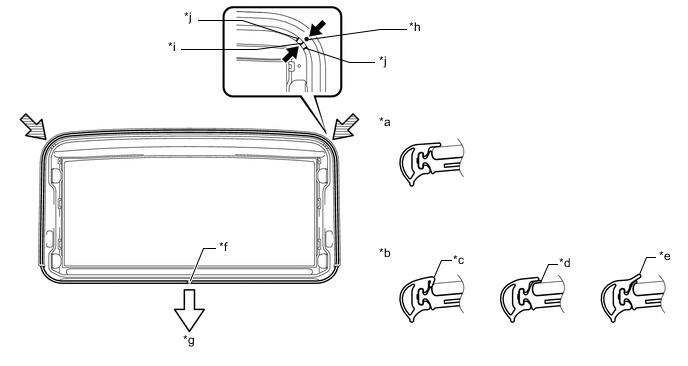
Text in Illustration *a Correct *b Incorrect *c Pinched *d Protruding *e Gap (raised, wavy, etc.) *f Joint *g Vehicle rear *h Alignment mark for sliding roof panel or removable roof weatherstrip *i Center mark on resin portion for each corner *j Edge mark on resin portion for each corner
-
-
-
INSTALL SLIDING ROOF GLASS SUB-ASSEMBLY
-
Using a T25 "TORX" socket wrench, temporarily install the sliding roof glass sub-assembly with the 4 screws.
-
Perform a level check.
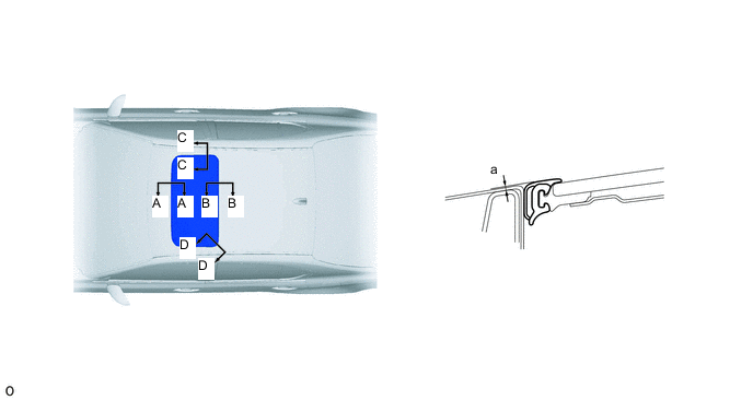
-
Check the difference in level for "a" between the roof panel and the upper surface of the weatherstrip when the sliding roof glass is fully closed.
Standard Area Measurement A - A 0 + 1.5 mm (0 + 0.0591 in.)
0 - 1.5 mm (0 - 0.0591 in.)
B - B 0 + 1.5 mm (0 + 0.0591 in.)
0 - 1.5 mm (0 - 0.0591 in.)
C - C 0 + 1.5 mm (0 + 0.0591 in.)
0 - 1.5 mm (0 - 0.0591 in.)
D - D 0 + 1.5 mm (0 + 0.0591 in.)
0 - 1.5 mm (0 - 0.0591 in.)
Tech Tips
"+" represents the condition that the glass is above the panel level. "-" represents the condition that the glass is below the panel level.
-
-
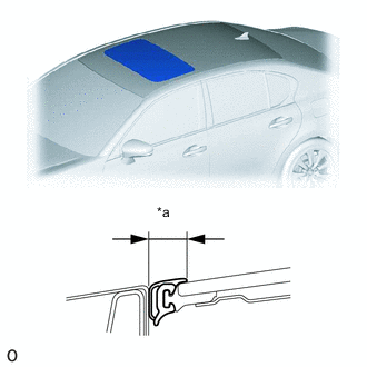
Text in Illustration *a Even Perform a gap check.
-
Check the gap between the roof panel and roof glass.
Note
The gap must be even all around.
-
-
After adjusting the sliding roof glass, using a T25 "TORX" socket wrench, install the sliding roof glass sub-assembly with the 4 screws.
- Torque:
- 5.5 N*m { 56 kgf*cm, 49 in.*lbf }
-
-
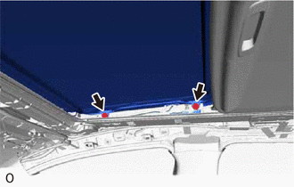
CHECK FOR WATER LEAK
-
After adjusting the sliding roof glass sub-assembly, check for water leakage into the vehicle interior.
-
If there are any leaks, readjust the sliding roof glass sub-assembly.
-
-
INSTALL SLIDING ROOF SIDE GARNISH LH
-
Attach the claws to install a new sliding roof side garnish LH.
-
-
INSTALL SLIDING ROOF SIDE GARNISH RH
Tech Tips
Use the same procedure described for the LH side.
-
INSTALL CURTAIN SHIELD AIRBAG ASSEMBLY LH
-
INSTALL CURTAIN SHIELD AIRBAG ASSEMBLY RH
Tech Tips
Use the same procedure described for the LH side.
-
INSTALL ROOF HEADLINING ASSEMBLY
-
CONNECT CABLE TO NEGATIVE AUXILIARY BATTERY TERMINAL
Note
When disconnecting the cable, some systems need to be initialized after the cable is reconnected Click here.
-
INSTALL LUGGAGE COMPARTMENT TRIM COVER LH
-
INSTALL LUGGAGE COMPARTMENT FLOOR MAT
-
CHECK SRS WARNING LIGHT
-
RESET SLIDING ROOF DRIVE GEAR SUB-ASSEMBLY
-
CHECK SLIDING ROOF SYSTEM