REAR SUNSHADE SYSTEM Front and Rear Switch Cannot Operate Rear Sunshade
DESCRIPTION
-
The rear window shade assembly receives the rear sun shade switch assembly signals and drives its built-in motor.
-
The rear window shade assembly receives the rear control switch (rear sunshade switch) signals and drives its built-in motor.
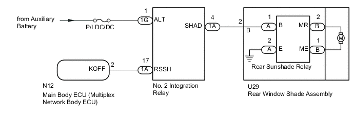
WIRING DIAGRAM
CAUTION / NOTICE / HINT
Note
-
Do not remove the ground bolt of the rear window shade assembly.
-
When the rear sunshade relay is replaced with a new one, do not use the wire harness packaged together with the new rear sunshade relay.
-
If the main body ECU (multiplex network body ECU) is replaced, refer to the Service Bulletin.
-
Inspect the fuses for circuits related to this system before performing the following inspection procedure.
PROCEDURE
-
CHECK NO. 2 INTEGRATION RELAY
-
Text in Illustration *a Front view of wire harness connector
(to Rear Window Shade Assembly)
Disconnect the rear window shade assembly connector.
-
Measure the voltage according to the value(s) in the table below.
Standard Voltage Tester Connection Condition Specified Condition U29-2 (B) - Body ground Within 60 seconds after power switch turned off, or power switch turned on (IG) again after 60 seconds have elapsed from time power switch turned off 11 to 14 V
NG 
CHECK HARNESS AND CONNECTOR (REAR WINDOW SHADE - NO. 2 INTEGRATION RELAY, BATTERY AND BODY GROUND) Click here
OK 
-
-
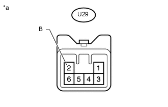
INSPECT REAR WINDOW SHADE ASSEMBLY
-
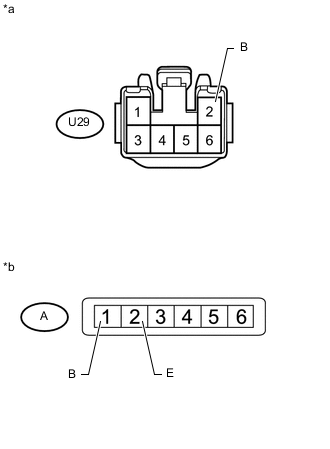
Text in Illustration *a Front view of wire harness connector
(Rear Window Shade Assembly)
*b Front view of wire harness connector
(Rear Window Shade Assembly)
Remove the rear window shade assembly Click here.
-
Disconnect the rear window shade assembly connector.
-
Disconnect the rear sunshade relay connector.
-
Measure the registance according to the value(s) in the table below.
Standard Resistance Tester Connection Condition Specified Condition U29-2 (B) - A-1 (B) Always Below 1 Ω U29-2 (B) - Body ground Always 10 kΩ or higher A-2 (E) - Body ground Always Below 1 Ω
NG 
REPLACE REAR WINDOW SHADE ASSEMBLY Click here
OK
-
-
CHECK REAR SUNSHADE RELAY
-
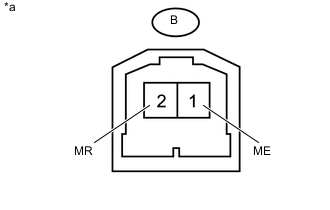
Text in Illustration *a Component with harness connected
(Rear Sunshade Relay)
Measure the voltage according to the value(s) in the table below.
Standard Voltage Tester Connection Condition Specified Condition B-2 (MR) - B-1 (MB) Rear sunshade lowered from fully raised position 11 to 14 V B-1 (ME) - B-2 (MR) Rear sunshade raised from fully lowered position 11 to 14 V
OK
REPLACE REAR WINDOW SHADE ASSEMBLY Click here
NG
REPLACE REAR SUNSHADE RELAY Click here
-
-
CHECK HARNESS AND CONNECTOR (REAR WINDOW SHADE - NO. 2 INTEGRATION RELAY, BATTERY AND BODY GROUND)
-
Disconnect the U29 rear window shade assembly connector.
-
Disconnect the 1A and 1G NO. 2 integration relay connectors.
-
Measure the resistance and voltage according to the value(s) in the table below.
Standard Resistance Tester Connection Condition Specified Condition U29-2 (B) - 1A-4 (SHAD) Always Below 1 Ω U29-2 (B) - Body ground Always 10 kΩ or higher Standard Voltage Tester Connection Condition Specified Condition 1G-1 (ALT) - Body ground Always 11 to 14 V
NG
REPAIR OR REPLACE HARNESS OR CONNECTOR
OK
-
-
CHECK HARNESS AND CONNECTOR (NO. 2 INTEGRATION RELAY - MAIN BODY ECU [MULTIPLEX NETWORK BODY ECU])
-
Disconnect the 1A NO. 2 integration relay connector.
-
Disconnect the N12 main body ECU (multiplex network body ECU) connector.
-
Measure the resistance according to the value(s) in the table below.
Standard Resistance Tester Connection Condition Specified Condition 1A-17 (RSSH) - N12-2 (KOFF) Always Below 1 Ω 1A-17 (RSSH) - Body ground Always 10 kΩ or higher
NG
REPAIR OR REPLACE HARNESS OR CONNECTOR
OK
-
-
REPLACE NO. 2 INTEGRATION RELAY
-
Temporarily replace the NO. 2 integration relay with a new or normally functioning one Click here.
NEXT
-
-
CHECK REAR SUNSHADE SYSTEM
-
Check the rear sunshade system.
OK Rear sunshade raises and lowers.
OK
END (NO. 2 INTEGRATION RELAY WAS DEFECTIVE)
NG
REPLACE MAIN BODY ECU (MULTIPLEX NETWORK BODY ECU) Click here
-