VEHICLE PROXIMITY NOTIFICATION SYSTEM The Sound does not Stop when The Engine is Operated or when The Shift Lever is in P
DESCRIPTION
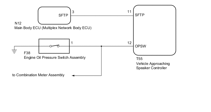
The vehicle approaching speaker controller receives shift position P signals from the main body ECU (multiplex network body ECU) and engine operation signals from the engine oil pressure switch assembly.
WIRING DIAGRAM
PROCEDURE
-
READ VALUE USING GTS (SHIFT POSITION)
-
Using the GTS, read the Data List Click here.
Vehicle Approaching Speaker Controller Tester Display Measurement Item/Range Normal Condition Diagnostic Note Shift Position Shift position P / Not Parking or Parking Not Parking: Shift lever not in P
Parking: Shift lever in P
- OK GTS display changes according to operation of the shift lever.
NG 
CHECK VEHICLE APPROACHING SPEAKER CONTROLLER Click here
OK 
-
-
READ VALUE USING GTS (OIL PRESSURE SW)
-
Using the GTS, read the Data List Click here.
Vehicle Approaching Speaker Controller Tester Display Measurement Item/Range Normal Condition Diagnostic Note Oil Pressure SW Engine oil pressure switch / OFF or ON OFF: Engine operate
ON: Engine not operate
- OK GTS display changes according to engine operation.
OK 
REPLACE VEHICLE APPROACHING SPEAKER CONTROLLER Click here
NG
CHECK ENGINE OIL PRESSURE SWITCH ASSEMBLY (OPSW SIGNAL) Click here
-
-
CHECK VEHICLE APPROACHING SPEAKER CONTROLLER
-
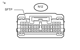
Text in Illustration *a Front view of wire harness connector
(to Main Body ECU [Multiplex Network Body ECU])
Disconnect the main body ECU (multiplex network body ECU) connector.
-
Measure the voltage according to the value (s) in the table below.
Standard Voltage Tester Connection Condition Specified Condition N12-3 (SFTP) - Body ground Power switch on (IG) 11 to 14 V Power switch off Below 1 V
NG
CHECK HARNESS AND CONNECTOR (VEHICLE APPROACHING SPEAKER CONTROLLER - MAIN BODY ECU [MULTIPLEX NETWORK BODY ECU]) Click here
OK
-
-
CHECK MAIN BODY ECU (MULTIPLEX NETWORK BODY ECU) (SFTP SIGNAL)
-
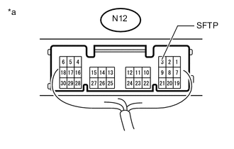
Text in Illustration *a Component with harness connected
(Main Body ECU [Multiplex Network Body ECU])
With the connector of the main body ECU (multiplex network body ECU) connector Click here.
-
Measure the voltage according to the value (s) in the table below.
Standard Voltage Tester Connection Condition Specified Condition N12-3 (SFTP) - Body ground Power switch on (IG), Shift lever in P Below 2.5 V Power switch on (IG), Shift lever not in P 8 V or higher
OK
REPLACE VEHICLE APPROACHING SPEAKER CONTROLLER Click here
NG
REPLACE MAIN BODY ECU (MULTIPLEX NETWORK BODY ECU) Click here
-
-
CHECK HARNESS AND CONNECTOR (VEHICLE APPROACHING SPEAKER CONTROLLER - MAIN BODY ECU [MULTIPLEX NETWORK BODY ECU])
-
Disconnect the T55 vehicle approaching speaker controller connector.
-
Disconnect the N12 main body ECU (multiplex network body ECU) connector.
-
Measure the resistance according to the value (s) in the table below.
Standard Resistance Tester Connection Condition Specified Condition T55-11 (SFTP) - N12-3 (SFTP) Always Below 1 Ω T55-11 (SFTP) or N12-3 (SFTP) - Body ground Always 10 kΩ or higher
OK
REPLACE VEHICLE APPROACHING SPEAKER CONTROLLER Click here
NG
REPAIR OR REPLACE HARNESS OR CONNECTOR
-
-
CHECK ENGINE OIL PRESSURE SWITCH ASSEMBLY (OPSW SIGNAL)
-
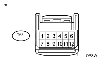
Text in Illustration *a Front view of wire harness connector
(to Vehicle Approaching Speaker Controller)
Disconnect the vehicle approaching speaker controller connector.
-
Measure the voltage according to the value(s) in the table below.
Standard Voltage Tester Connection Condition Specified Condition T55-12 (OPSW) - Switch body Idling* 8 V or higher Power switch on (IG) Below 2.0 V *: Enter vehicle preparation mode, and then perform the inspection Click here.
OK
REPLACE VEHICLE APPROACHING SPEAKER CONTROLLER Click here
NG
-
-
CHECK HARNESS AND CONNECTOR (VEHICLE APPROACHING SPEAKER CONTROLLER - ENGINE OIL PRESSURE SWITCH ASSEMBLY)
-
Disconnect the T55 vehicle approaching speaker controller connector.
-
Disconnect the F38 engine oil pressure switch assembly connector.
-
Measure the resistance according to the value (s) in the table below.
Standard Resistance Tester Connection Condition Specified Condition T55-12 (OPSW) - F38-1 Always Below 1 Ω T55-12 (OPSW) or F38-1 - Body ground Always 10 kΩ or higher
OK
REPLACE ENGINE OIL PRESSURE SWITCH ASSEMBLY Click here
NG
REPAIR OR REPLACE HARNESS OR CONNECTOR
-