ELECTRONICALLY CONTROLLED BRAKE SYSTEM, Diagnostic DTC:C1246/46, C1281/81, C1364/61

| DTC Code | DTC Name |
|---|---|
| C1246/46 | Master Cylinder Pressure Sensor Malfunction |
| C1281/81 | Master Cylinder Pressure Sensor Output Malfunction (Test Mode DTC) |
| C1364/61 | Wheel Cylinder Pressure Sensor Malfunction |
DESCRIPTION
The master cylinder pressure sensor and the wheel cylinder pressure sensor are built into the brake actuator. They measure the master cylinder pressure and wheel cylinder pressure and send the data to the skid control ECU.
DTC C1281/81 can be deleted when the master cylinder pressure sensor sends a master cylinder pressure signal or the Test Mode ends. DTC C1281/81 is output only in the Test Mode.
| DTC Code | Information Code | DTC Detection Condition | Trouble Area |
|---|---|---|---|
| C1246/46 | 191 | Sensor power source 1 (VCM) voltage is less than 4.7 V or 5.3 V or more for at least 0.05 seconds. |
|
| ↑ | 192 | Master cylinder pressure sensor output voltage 1 (PMC1) is less than 0.25 V or 4.53 V or more for at least 0.05 seconds. |
|
| ↑ | 194 | Sensor power source 2 (VCM2) voltage is less than 4.7 V or 5.3 V or more for at least 0.05 seconds. |
|
| ↑ | 195 | Master cylinder pressure sensor output voltage 2 (PMC2) is less than 0.25 V or 4.53 V or more for at least 0.05 seconds. |
|
| ↑ | 197 | Master cylinder pressure sensor output voltage 1 (PMC1) is abnormal. | ↑ |
| ↑ | 198 | Master cylinder pressure sensor output voltage 2 (PMC2) is abnormal. | ↑ |
| ↑ | 199 | Master cylinder pressure sensor output voltage 1 (PMC1) is less than 0.33 V or 0.85 V or more when not braking. |
|
| ↑ | 200 | Master cylinder pressure sensor output voltage 2 (PMC2) is less than 0.33 V or 0.85 V or more when not braking. | ↑ |
| ↑ | 201 | PMC1 and PMC2 voltages are different. | ↑ |
| ↑ | 202 | Condition that output voltage of front pressure sensor LH (PFL) and rear pressure sensor RH (PRR) is 0.25 V or less or 4.53 V or more continues for 0.05 seconds or more |
|
| ↑ | 205 | Condition that output voltage of front pressure sensor RH (PFR) and rear pressure sensor LH (PRL) is 0.25 V or less or 4.53 V or more continues for 0.05 seconds or more | ↑ |
| C1364/61 | 221 | Sensor power source 1 (VCM1) voltage is less than 4.7 V or 5.3 V or more for at least 0.05 seconds. |
|
| ↑ | 222 | Front wheel cylinder pressure sensor RH output voltage (PFR) is less than 0.25 V or 4.53 V or more for at least 0.05 seconds. |
|
| ↑ | 224 | Front wheel cylinder pressure sensor RH output (PFR) is less than 0.33 V or more 0.85 V or more when not braking. | ↑ |
| ↑ | 225 | The PFR output voltage is stuck at 4.53 V or less. | ↑ |
| ↑ | 227 | Sensor power source 2 (VCM2) voltage is less than 4.7 V or 5.3 V or more for at least 0.05 seconds. |
|
| ↑ | 228 | Front wheel cylinder pressure sensor LH output voltage (PFL) is less than 0.25 V or 4.53 V or more for at least 0.05 seconds. |
|
| ↑ | 230 | Front wheel cylinder pressure sensor LH output (PFL) is less than 0.33 V or 0.85 V or more when not braking. | ↑ |
| ↑ | 231 | The PFL output voltage is stuck at 4.53 V or less. | ↑ |
| ↑ | 233 | Sensor power source 2 (VCM2) voltage is less than 4.7 V or 5.3 V or more for at least 0.05 seconds. |
|
| ↑ | 234 | Rear wheel cylinder pressure sensor RH output voltage (PRR) is less than 0.25 V or 4.53 V or more for at least 0.05 seconds. |
|
| ↑ | 236 | Rear wheel cylinder pressure sensor RH output (PRR) is less than 0.33 V or 0.85 V or more when not braking. | ↑ |
| ↑ | 237 | The PRR output voltage is stuck at 4.53 V or less. | ↑ |
| ↑ | 239 | Sensor power source 1 (VCM1) voltage is less than 4.7 V or 5.3 V or more for at least 0.05 seconds. |
|
| ↑ | 240 | Rear wheel cylinder pressure sensor LH output voltage (PRL) is less than 0.25 V or 4.53 V or more for at least 0.05 seconds. |
|
| ↑ | 242 | Rear wheel cylinder pressure sensor LH output (PRL) is less than 0.33 V or 0.85 V or more when not braking. | ↑ |
| ↑ | 243 | The PRL output voltage is stuck at 4.53 V or less. | ↑ |
| C1281/81 | - | Detected only during test mode. |
|
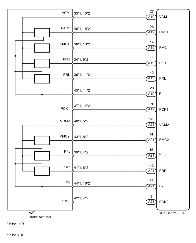
WIRING DIAGRAM
CAUTION / NOTICE / HINT
Note
-
When replacing the skid control ECU, perform the following operations:
-
Initialization of linear solenoid valve and calibration Click here
-
Yaw rate and acceleration sensor zero point calibration Click here
-
When replacing the brake actuator, perform initialization of the linear solenoid valve and calibration Click here.
PROCEDURE
-
CHECK HARNESS AND CONNECTOR (SKID CONTROL ECU - BRAKE ACTUATOR)
-
Disconnect the A19 and A21 ECU connectors.
-
Disconnect the A27 actuator connector.
-
Measure the resistance according to the value(s) in the table below.
Standard resistance for LHD: Tester Connection Condition Specified Condition A19-9 (PCK1) - A27-37 (PCK1) Always Below 1 Ω A19-14 (PMC1) - A27-38 (PMC1) Always Below 1 Ω A19-26 (PAC1) - A27-46 (PAC1) Always Below 1 Ω A19-27 (VCM) - A27-35 (VCM) Always Below 1 Ω A19-42 (PRL) - A27-36 (PRL) Always Below 1 Ω A19-28 (E) - A27-45 (E) Always Below 1 Ω A19-44 (PFR) - A27-34 (PFR) Always Below 1 Ω A21-7 (PCK2) - A27-42 (PCK2) Always Below 1 Ω A21-14 (PMC2) - A27-43 (PMC2) Always Below 1 Ω A21-28 (VCM2) - A27-40 (VCM2) Always Below 1 Ω A21-43 (PRR) - A27-41 (PRR) Always Below 1 Ω A21-44 (E2) - A27-44 (E2) Always Below 1 Ω A21-45 (PFL) - A27-39 (PFL) Always Below 1 Ω A19-9 (PCK1) - Body ground Always 10 kΩ or higher A19-14 (PMC1) - Body ground Always 10 kΩ or higher A19-26 (PAC1) - Body ground Always 10 kΩ or higher A19-27 (VCM) - Body ground Always 10 kΩ or higher A19-42 (PRL) - Body ground Always 10 kΩ or higher A19-28 (E) - Body ground Always 10 kΩ or higher A19-44 (PFR) - Body ground Always 10 kΩ or higher A21-7 (PCK2) - Body ground Always 10 kΩ or higher A21-14 (PMC2) - Body ground Always 10 kΩ or higher A21-28 (VCM2) - Body ground Always 10 kΩ or higher A21-43 (PRR) - Body ground Always 10 kΩ or higher A21-44 (E2) - Body ground Always 10 kΩ or higher A21-45 (PFL) - Body ground Always 10 kΩ or higher Standard resistance for RHD: Tester Connection Condition Specified Condition A19-9 (PCK1) - A27-12 (PCK1) Always Below 1 Ω A19-14 (PMC1) - A27-13 (PMC1) Always Below 1 Ω A19-26 (PAC1) - A27-15 (PAC1) Always Below 1 Ω A19-27 (VCM) - A27-10 (VCM) Always Below 1 Ω A19-42 (PRL) - A27-11 (PRL) Always Below 1 Ω A19-28 (E) - A27-14 (E) Always Below 1 Ω A19-44 (PFR) - A27-9 (PFR) Always Below 1 Ω A21-7 (PCK2) - A27-7 (PCK2) Always Below 1 Ω A21-14 (PMC2) - A27-8 (PMC2) Always Below 1 Ω A21-28 (VCM2) - A27-5 (VCM2) Always Below 1 Ω A21-43 (PRR) - A27-6 (PRR) Always Below 1 Ω A21-44 (E2) - A27-16 (E2) Always Below 1 Ω A21-45 (PFL) - A27-4 (PFL) Always Below 1 Ω A19-9 (PCK1) - Body ground Always 10 kΩ or higher A19-14 (PMC1) - Body ground Always 10 kΩ or higher A19-26 (PAC1) - Body ground Always 10 kΩ or higher A19-27 (VCM) - Body ground Always 10 kΩ or higher A19-42 (PRL) - Body ground Always 10 kΩ or higher A19-28 (E) - Body ground Always 10 kΩ or higher A19-44 (PFR) - Body ground Always 10 kΩ or higher A21-7 (PCK2) - Body ground Always 10 kΩ or higher A21-14 (PMC2) - Body ground Always 10 kΩ or higher A21-28 (VCM2) - Body ground Always 10 kΩ or higher A21-43 (PRR) - Body ground Always 10 kΩ or higher A21-44 (E2) - Body ground Always 10 kΩ or higher A21-45 (PFL) - Body ground Always 10 kΩ or higher
NG 
REPAIR OR REPLACE HARNESS OR CONNECTOR
OK 
-
-
READ VALUE USING INTELLIGENT TESTER (MASTER CYLINDER PRESSURE SENSOR)
-
Connect the intelligent tester to the DLC3.
-
Turn the power switch ON (IG).
-
Select the DATA LIST mode on the intelligent tester.
ABS/VSC/TRAC: Tester Display Measurement Item/Range Normal Condition Diagnostic Note Voltage of Master Cylinder Sensor Master cylinder pressure sensor 1 reading / min.: 0 V, max.: 5 V When brake pedal is released:
0.3 to 0.9 V
Reading increases when brake pedal is depressed Voltage of Master Cylinder Sensor 2 Master cylinder pressure sensor 2 reading / min.: 0 V, max.: 5 V When brake pedal is released:
0.3 to 0.9 V
Reading increases when brake pedal is depressed -
Check the output value of the master cylinder pressure sensor on the intelligent tester display.
OK When the pedal is depressed, the voltage displayed on the intelligent tester increases. Result Result Proceed to OK A NG for LHD B for RHD C
B
REPLACE BRAKE ACTUATOR Click here
C
REPLACE BRAKE ACTUATOR Click here
A
-
-
CHECK PRESSURE SENSOR OPERATION
-
for LHD:
Check the pressure sensor operation Click here.
for RHD:
Check the pressure sensor operation Click here.
Result Result Proceed to OK A NG for LHD B for RHD C
B
REPLACE BRAKE ACTUATOR Click here
C
REPLACE BRAKE ACTUATOR Click here
A
-
-
RECONFIRM DTC
-
Clear the DTC Click here.
-
Perform the road and braking test.
-
Check if the same DTCs are recorded Click here.
Tech Tips
Reinstall the sensors, connectors, etc. and restore the vehicle to its prior condition before rechecking for DTCs.
Result Result Proceed to DTCs (C1246/46 and C1364/61) are output A DTCs (C1246/46 and C1364/61) are not output B
B
USE SIMULATION METHOD TO CHECK Click here
A
-
-
CHECK FREEZE FRAME DATA
-
Check the information code from the "FREEZE FRAME DATA" memorized when the DTCs (C1246/46 and C1364/61) are stored Click here.
Result Result Proceed to Sensor power supply malfunction codes (191, 194, 221, 227, 233 and 239) are output for LHD A for RHD B Sensor output malfunction codes (except 191, 194, 221, 227, 233 and 239) are output for LHD C for RHD D
A
REPLACE SKID CONTROL ECU Click here
B
REPLACE SKID CONTROL ECU Click here
C
REPLACE BRAKE ACTUATOR Click here
D
REPLACE BRAKE ACTUATOR Click here
-