МАСЛЯНЫЙ НАСОС УСТАНОВКА

PROCEDURE
-
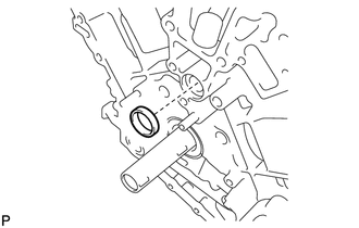
INSTALL WATER INLET PIPE
-
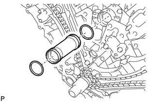
Apply soapy water to 2 new O-rings and install them to the inlet pipe.
-
Install the inlet pipe to the No. 1 heat exchanger cover.
-
-
INSTALL TIMING CHAIN COVER SUB-ASSEMBLY
-
Install a new oil pump gasket.
-
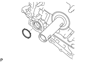
Install a new O-ring.
-
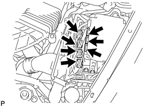
Apply seal packing in a continuous line to the timing chain cover as shown in the following illustration.
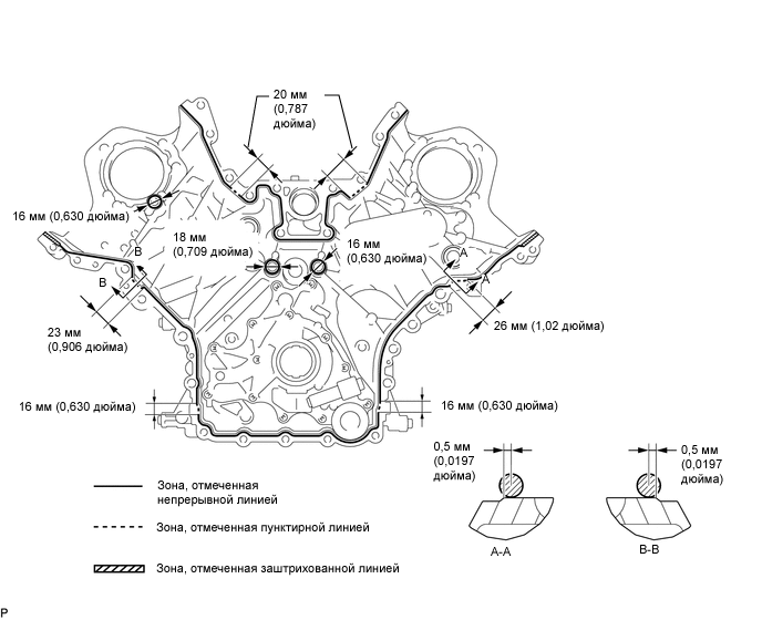
Seal packing Toyota Genuine Seal Packing Black, Three Bond 1207B or equivalent
-
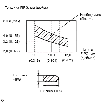
Apply Seal Packing as Follows Area Seal packing diameter Application position from inside edge of cover Continuous Line Area 3.0 to 4.0 mm (0.1181 to 0.1575 in.) 2.5 mm (0.098 in.) Dashed Line Area 6.4 mm (0.2520 in.) or more, or within OK area shown in illustration 0.5 mm (0.020 in.) Diagonal Line Area 3.0 to 4.0 mm (0.1181 to 0.1575 in.) 5.5 mm (0.217 in.)
Note
-
When the contact surfaces are wet, wipe them with an oil-free cloth before applying seal packing.
-
Install the chain cover within 3 minutes and tighten the bolts within 10 minutes after applying seal packing.
-
Do not start the engine for at least 2 hours after installation.
-
-
Align the drive rotor spline of the oil pump and the crankshaft as shown in the illustration. Install the spline and chain cover to the crankshaft.
-
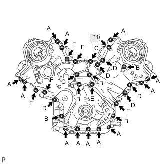
*1 Nut Temporarily tighten the timing chain cover with the 30 bolts and nut.
Bolt Length Item Length Thread diameter Bolt A 25 mm (0.984 in.) 8 mm (0.315 in.) Bolt B 55 mm (2.165 in.) 8 mm (0.315 in.) Bolt C 70 mm (2.756 in.) 8 mm (0.315 in.) Bolt D 35 mm (1.378 in.) 10 mm (0.394 in.) Bolt E 55 mm (2.165 in.) 10 mm (0.394 in.) Bolt F 80 mm (3.150 in.) 10 mm (0.394 in.) Note
Make sure that there is no oil on the bolt threads.
-
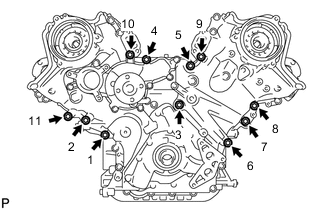
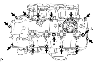
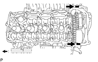
Tighten the 11 bolts in several steps, in the sequence shown in the illustration.
- Torque:
- 47 N*m { 479 kgf*cm, 35 ft.*lbf }
-
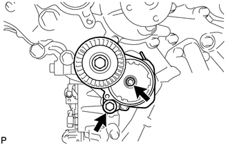
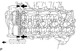
Temporarily tighten the belt tensioner with the standard bolt and 6 mm hexagon wrench bolt.
-
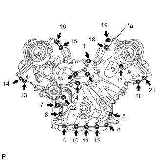
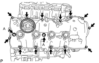
*a Nut Tighten the 21 bolts and nut in several steps, in the sequence shown in the illustration.
- Torque:
- 23 N*m { 235 kgf*cm, 17 ft.*lbf }
Note
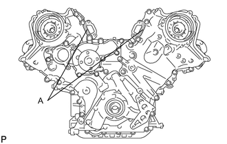
After the installation, if the seal packing has seeped out at the areas labeled A shown in the illustration, wipe it off.
-
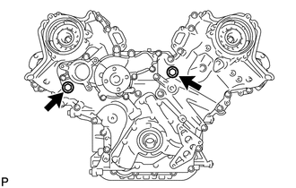
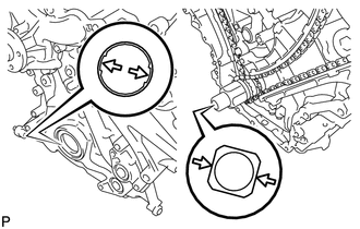
Install the 2 new gaskets and the 2 plugs.
- Torque:
- 46 N*m { 469 kgf*cm, 34 ft.*lbf }
-
-
INSTALL CYLINDER HEAD COVER SUB-ASSEMBLY (for Bank 1)
-
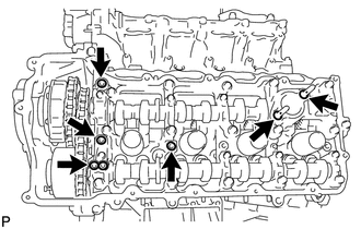
Install 4 new gaskets and 2 new O-rings to the camshaft bearing caps (No. 2, No. 3, No. 7).
-
Install a new gasket to the cylinder head cover.
Note
Remove any oil from the contact surface.
-
*1 Seal Packing Apply seal packing as shown in the illustration.
Seal packing Toyota Genuine Seal Packing Black, Three Bond 1207B or equivalent Note
-
Remove any oil from the contact surface.
-
Install the cylinder head cover within 3 minutes and tighten the bolts within 15 minutes after applying seal packing.
-
Do not start the engine for at least 2 hours after the installation.
-
-
Install the cylinder head cover with 2 new seal washers and the 15 bolts.
- Torque:
- for bolt A
- 21 N*m { 214 kgf*cm, 15 ft.*lbf }
- except bolt A
- 12 N*m { 122 kgf*cm, 9 ft.*lbf }
-
-
INSTALL CYLINDER HEAD COVER SUB-ASSEMBLY (for Bank 2)
-
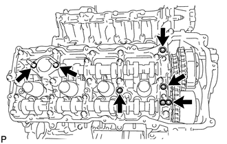
Install 4 new gaskets and 2 new O-rings to the camshaft bearing caps (No. 1, No. 3, No. 6).
-
Install a new gasket to the cylinder head cover.
Note
Remove any oil from the contact surface.
-
*1 Seal Packing Apply seal packing as shown in the illustration.
Seal packing Toyota Genuine Seal Packing Black, Three Bond 1207B or equivalent Note
-
Remove any oil from the contact surface.
-
Install the cylinder head cover within 3 minutes and tighten the bolts within 15 minutes after applying seal packing.
-
Do not start the engine for at least 2 hours after the installation.
-
-
Install the cylinder head cover with 2 new seal washers and the 15 bolts.
- Torque:
- for bolt A
- 21 N*m { 214 kgf*cm, 15 ft.*lbf }
- except bolt A
- 12 N*m { 122 kgf*cm, 9 ft.*lbf }
-
-
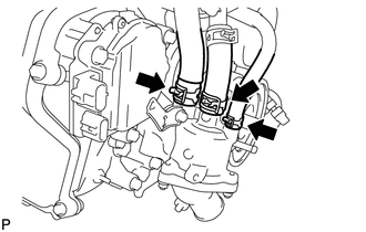
INSTALL IGNITION COIL ASSEMBLY
-
INSTALL CRANKSHAFT PULLEY
-
Align the pulley set key with the key groove of the pulley, and slide on the pulley.
-
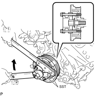
*1 Hold *2 Turn Using SST, install the pulley bolt.
- SST
- 09213-54015 ( 90119-08216 )
- 09330-00021
- Torque:
- 300 N*m { 3059 kgf*cm, 221 ft.*lbf }
-
-
INSTALL RESONATOR BRACKET SUB-ASSEMBLY
-
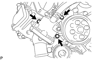
INSTALL OIL FILTER BRACKET
-
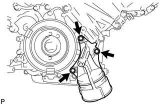
Install 2 new gaskets and the filter bracket with the 3 bolts.
- Torque:
- 21 N*m { 214 kgf*cm, 15 ft.*lbf }
-
-
INSTALL OIL FILTER ELEMENT
-
INSTALL CAMSHAFT TIMING CONTROL MOTOR ASSEMBLY LH (for Bank 1)
-
INSTALL CAMSHAFT TIMING CONTROL MOTOR ASSEMBLY (for Bank 2)
-
INSTALL FRONT WATER BY-PASS JOINT
-
INSTALL NO. 1 IDLER PULLEY SUB-ASSEMBLY
-
INSTALL NO. 2 IDLER PULLEY SUB-ASSEMBLY
-
INSTALL WATER PUMP PULLEY
-
INSTALL WATER INLET HOUSING
-
Install the inlet housing and new gasket with the 3 bolts.
- Torque:
- 21 N*m { 214 kgf*cm, 15 ft.*lbf }
-
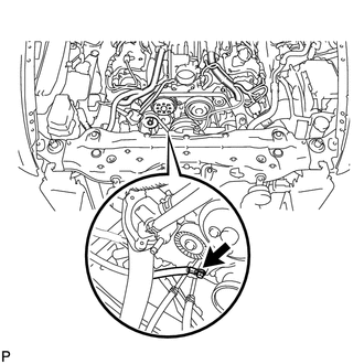
Using needle-nose pliers, grip the claws of the clips and slide the clips to connect the water by-pass hoses and water inlet hose.
-
-
INSTALL NO. 2 ENGINE COVER SUB-ASSEMBLY LH
-
INSTALL NO. 3 ENGINE COVER
-
INSTALL INTAKE MANIFOLD
-
INSTALL WATER BY-PASS PIPE SUB-ASSEMBLY
-
INSTALL GENERATOR ASSEMBLY
-
INSTALL ENGINE OIL LEVEL DIPSTICK GUIDE
-
CONNECT COOLER COMPRESSOR ASSEMBLY
-
INSTALL EXHAUST MANIFOLD SUB-ASSEMBLY LH
-
INSTALL NO. 2 EXHAUST MANIFOLD HEAT INSULATOR
-
INSTALL NO. 2 STEERING INTERMEDIATE SHAFT ASSEMBLY
-
INSTALL STEERING SLIDING YOKE WITH SHAFT SUB-ASSEMBLY (w/ VGRS)
-
INSTALL STEERING SLIDING YOKE WITH SHAFT SUB-ASSEMBLY (w/o VGRS)
-
INSTALL FRONT SUSPENSION MEMBER REINFORCEMENT LH
-
INSTALL FRONT STABILIZER BAR
-
INSTALL FRONT EXHAUST PIPE ASSEMBLY
-
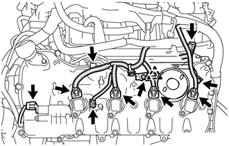
CONNECT ENGINE WIRE
-
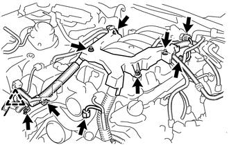
Connect the engine wire with the 4 nuts.
- Torque:
- 10 N*m { 102 kgf*cm, 7 ft.*lbf }
-
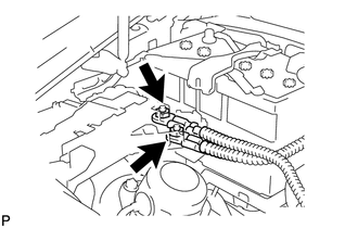
Connect the clamp and install the 2 clamp brackets with the 2 bolts.
- Torque:
- 10 N*m { 102 kgf*cm, 7 ft.*lbf }
-
Connect the intake air control valve actuator connector.
-
Connect the No. 1 vacuum switching valve connector.
-
Connect the ground wire with the bolt.
- Torque:
- 21 N*m { 214 kgf*cm, 15 ft.*lbf }
-
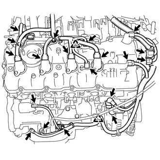
for Engine Room RH Side:
-
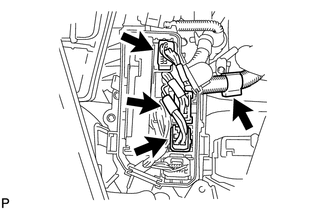
Connect the 2 clamps and install the 3 clamp brackets with the 3 bolts.
- Torque:
- 10 N*m { 102 kgf*cm, 7 ft.*lbf }
-
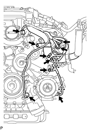
Connect the engine oil level sensor connector.
-
Connect the crankshaft position sensor connector.
-
Connect the starter connector and starter wire with the nut.
- Torque:
- 10 N*m { 102 kgf*cm, 7 ft.*lbf }
-
Connect the generator connector and generator wire with the nut.
- Torque:
- 12 N*m { 122 kgf*cm, 9 ft.*lbf }
-
Connect the camshaft position sensor connector.
-
Connect the engine wire connector.
-
Connect the 2 camshaft timing control motor connectors. (for Bank 2)
-
Connect the 2 VVT sensor connectors.
-
Connect the 4 ignition coil connectors.
-
Connect the camshaft timing control valve connector.
-
Connect the wires to the No. 1 engine room junction block with the 2 nuts.
- Torque:
- 13 N*m { 133 kgf*cm, 10 ft.*lbf }
-
Connect the 3 connectors to the front controller with the clamp.
-
-
for Engine Room LH Side:
-
Install the clamp bracket with the bolt.
- Torque:
- 10 N*m { 102 kgf*cm, 7 ft.*lbf }
-
Connect the 3 clamps and 3 ground wires with the 3 bolts.
- Torque:
- 10 N*m { 102 kgf*cm, 7 ft.*lbf }
-
Attach the clamp and connect the cooler compressor connector.
-
Connect the 2 camshaft timing control motor connectors. (for Bank 1)
-
Connect the engine oil pressure sensor connector.
-
Connect the engine coolant temperature sensor connector.
-
Connect the clamp and install the 2 clamp brackets with the 2 bolts.
- Torque:
- 10 N*m { 102 kgf*cm, 7 ft.*lbf }
-
Connect the No. 8 engine wire connector.
-
Connect the 2 VVT sensor connectors.
-
Connect the 4 ignition coil connectors.
-
Connect the camshaft timing control valve connector.
-
Connect the 3 ECT connectors and 4 ECM connectors.
-
Install the ECM box cover (upper).
-
-
-
INSTALL ENGINE ROOM ECU OUTLET DUCT
-
INSTALL SKID CONTROL ECU BRACKET
-
CONNECT NO. 2 RADIATOR HOSE
-
CONNECT NO. 1 RADIATOR HOSE
-
INSTALL V-RIBBED BELT
-
INSTALL RADIATOR RESERVOIR ASSEMBLY
-
INSTALL AIR CLEANER ASSEMBLY LH
-
INSTALL AIR CLEANER ASSEMBLY RH
-
INSTALL INTAKE AIR CONNECTOR PIPE
-
INSTALL NO. 1 AIR CLEANER INLET
-
INSTALL ENGINE UNDER COVER REAR LH
-
INSTALL ENGINE UNDER COVER REAR RH
-
INSTALL BATTERY TRAY
-
Install the battery tray with the 3 bolts.
- Torque:
- 5.4 N*m { 55 kgf*cm, 48 in.*lbf }
-
Install the battery and battery insulator.
-
-
INSTALL BATTERY CLAMP SUB-ASSEMBLY
-
Install the battery clamp and 2 clamp bolts with the nut.
- Torque:
- 5.4 N*m { 55 kgf*cm, 48 in.*lbf }
-
-
ADD ENGINE OIL
-
ADD ENGINE COOLANT
-
CONNECT CABLE TO NEGATIVE BATTERY TERMINAL
Note
When disconnecting the cable, some systems need to be initialized after the cable is reconnected Click here.
-
INSPECT FOR OIL LEAK
-
INSPECT FOR COOLANT LEAK
-
INSPECT FOR EXHAUST GAS LEAK
-
CHECK ENGINE OIL LEVEL
-
INSTALL FRONT SUSPENSION MEMBER PROTECTOR LOWER
-
INSTALL NO. 2 ENGINE UNDER COVER
-
INSTALL NO. 1 ENGINE UNDER COVER
-
INSTALL ENGINE ROOM SIDE COVER RH
-
INSTALL ENGINE ROOM SIDE COVER LH
-
INSTALL AIR CLEANER INLET COVER SUB-ASSEMBLY
-
INSTALL V-BANK COVER SUB-ASSEMBLY
-
INSTALL COWL TOP VENTILATOR LOUVER RH