МАСЛЯНЫЙ НАСОС СНЯТИЕ

PROCEDURE
-
DISCHARGE FUEL SYSTEM PRESSURE
-
REMOVE COWL TOP VENTILATOR LOUVER RH
-
PRECAUTION
Note
After turning the engine switch off, waiting time may be required before disconnecting the cable from the battery terminal. Therefore, make sure to read the disconnecting the cable from the battery terminal notice before proceeding with work Click here.
-
DISCONNECT CABLE FROM NEGATIVE BATTERY TERMINAL
Note
When disconnecting the cable, some systems need to be initialized after the cable is reconnected Click here.
-
REMOVE V-BANK COVER SUB-ASSEMBLY
-
REMOVE AIR CLEANER INLET COVER SUB-ASSEMBLY
-
REMOVE NO. 1 AIR CLEANER INLET
-
REMOVE ENGINE ROOM SIDE COVER LH
-
REMOVE ENGINE ROOM SIDE COVER RH
-
REMOVE BATTERY CLAMP SUB-ASSEMBLY
-
Remove the nut, battery clamp and 2 clamp bolts.
-
-
REMOVE BATTERY TRAY
-
Remove the battery insulator and battery.
-
Remove the 3 bolts and battery tray.
-
-
REMOVE NO. 1 ENGINE UNDER COVER
-
REMOVE NO. 2 ENGINE UNDER COVER
-
REMOVE FRONT SUSPENSION MEMBER PROTECTOR LOWER
-
REMOVE ENGINE UNDER COVER REAR LH
-
REMOVE ENGINE UNDER COVER REAR RH
-
DRAIN ENGINE OIL
-
DRAIN ENGINE COOLANT
-
REMOVE INTAKE AIR CONNECTOR PIPE
-
REMOVE AIR CLEANER ASSEMBLY RH
-
REMOVE AIR CLEANER ASSEMBLY LH
-
REMOVE RADIATOR RESERVOIR ASSEMBLY
-
REMOVE V-RIBBED BELT
-
DISCONNECT NO. 1 RADIATOR HOSE
-
DISCONNECT NO. 2 RADIATOR HOSE
-
REMOVE ENGINE ROOM ECU OUTLET DUCT
-
REMOVE SKID CONTROL ECU BRACKET
-
DISCONNECT ENGINE WIRE
-
for Engine Room LH Side:
-
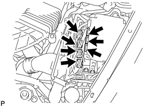
Remove the ECM box cover (upper).
-
Disconnect the 3 ECT connectors and 4 ECM connectors from the ECM box.
-
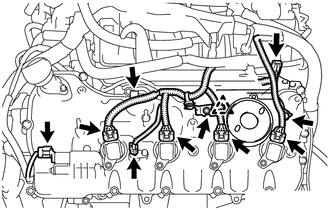
Disconnect the camshaft timing control valve connector.
-
Disconnect the 4 ignition coil connectors.
-
Disconnect the 2 VVT sensor connectors.
-
Disconnect the No. 8 engine wire connector.
-
Remove the 2 bolts and disconnect the clamp and 2 clamp brackets.
-
Disconnect the engine coolant temperature sensor connector.
-
Disconnect the engine oil pressure sensor connector.
-
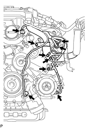
Disconnect the 2 camshaft timing control motor connectors. (for Bank 1)
-
Detach the clamp and disconnect the cooler compressor connector.
-
Remove the 3 bolts and disconnect the 3 clamps and ground wire.
-
Remove the bolt and clamp bracket.
-
-
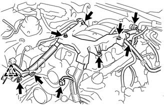
for Engine Room RH Side:
-
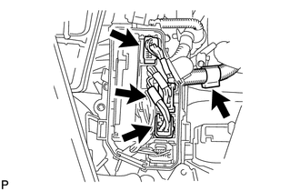
Detach the clamp and disconnect the 3 connectors from the front controller.
-
Remove the 2 nuts and disconnect the wires from the No. 1 engine room junction block.
-
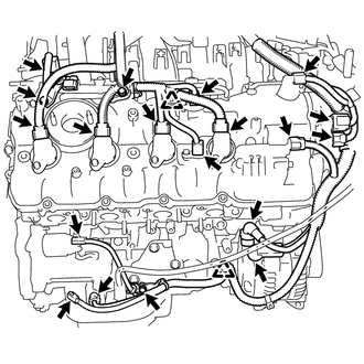
Disconnect the camshaft timing control valve connector.
-
Disconnect the 4 ignition coil connectors.
-
Disconnect the 2 VVT sensor connectors.
-
Disconnect the engine wire connector.
-
Disconnect the 2 camshaft timing control motor connectors. (for Bank 2)
-
Disconnect the camshaft position sensor connector.
-
Remove the nut and disconnect the generator wire and connector.
-
Remove the nut and disconnect the starter wire and connector.
-
Disconnect the crankshaft position sensor connector.
-
Disconnect the engine oil level sensor connector.
-
Remove the 3 bolts, and disconnect the 3 clamp brackets and 2 clamps.
-
-
Remove the bolt and disconnect the ground wire.
-
Disconnect the No. 1 vacuum switching valve connector.
-
Disconnect the intake air control valve actuator connector.
-
Remove the 2 bolts and disconnect the 2 clamp brackets and clamp.
-
Remove the 4 nuts and disconnect the engine wire.
-
-
REMOVE FRONT EXHAUST PIPE ASSEMBLY
-
REMOVE FRONT STABILIZER BAR
-
REMOVE FRONT SUSPENSION MEMBER REINFORCEMENT LH
-
REMOVE STEERING SLIDING YOKE WITH SHAFT SUB-ASSEMBLY (w/ VGRS)
-
REMOVE STEERING SLIDING YOKE WITH SHAFT SUB-ASSEMBLY (w/o VGRS)
-
REMOVE NO. 2 STEERING INTERMEDIATE SHAFT ASSEMBLY
-
REMOVE NO. 2 EXHAUST MANIFOLD HEAT INSULATOR
-
REMOVE EXHAUST MANIFOLD SUB-ASSEMBLY LH
-
DISCONNECT COOLER COMPRESSOR ASSEMBLY
-
REMOVE ENGINE OIL LEVEL DIPSTICK GUIDE
-
REMOVE GENERATOR ASSEMBLY
-
REMOVE WATER BY-PASS PIPE SUB-ASSEMBLY
-
REMOVE INTAKE MANIFOLD
-
REMOVE NO. 3 ENGINE COVER
-
REMOVE NO. 2 ENGINE COVER SUB-ASSEMBLY LH
-
REMOVE WATER INLET HOUSING
-
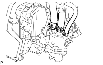
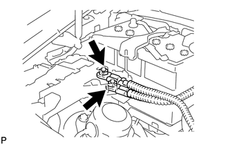
Using needle-nose pliers, grip the claws of the clips and slide the clips to disconnect the water by-pass hoses and water inlet hose.
-
Remove the 3 bolts, water inlet housing and gasket.
-
-
REMOVE WATER PUMP PULLEY
-
REMOVE NO. 2 IDLER PULLEY SUB-ASSEMBLY
-
REMOVE NO. 1 IDLER PULLEY SUB-ASSEMBLY
-
REMOVE FRONT WATER BY-PASS JOINT
-
REMOVE CAMSHAFT TIMING CONTROL MOTOR ASSEMBLY LH (for Bank 1)
-
REMOVE CAMSHAFT TIMING CONTROL MOTOR ASSEMBLY (for Bank 2)
-
REMOVE OIL FILTER ELEMENT
-
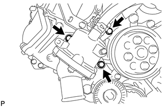
REMOVE OIL FILTER BRACKET
-
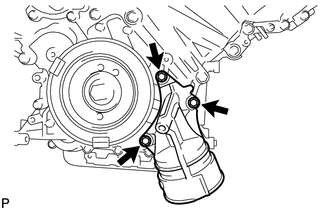
Remove the 3 bolts, filter bracket and 2 gaskets.
-
-
REMOVE RESONATOR BRACKET SUB-ASSEMBLY
-
REMOVE CRANKSHAFT PULLEY
-
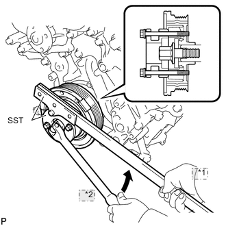
*1 Hold *2 Turn Using SST, loosen the crankshaft pulley set bolt.
- SST
- 09213-54015 ( 90119-08216 )
- 09330-00021
-
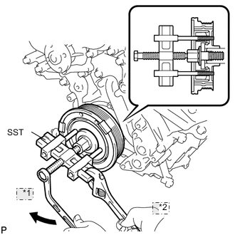
*1 Turn *2 Hold Using the pulley set bolt and SST, remove the crankshaft pulley.
- SST
- 09950-50013 ( 09951-05010, 09952-05010, 09953-05010, 09954-05010 )
-
-
REMOVE IGNITION COIL ASSEMBLY
-
REMOVE CYLINDER HEAD COVER SUB-ASSEMBLY (for Bank 1)
-
Remove the 15 bolts, 2 seal washers, cylinder head cover and gasket.
Tech Tips
Make sure the removed parts are returned to the same places they were removed from.
-
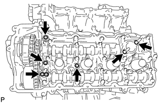
Remove the 4 gaskets and 2 O-rings from the camshaft bearing caps (No. 2, No. 3, No. 7).
-
-
REMOVE CYLINDER HEAD COVER SUB-ASSEMBLY (for Bank 2)
-
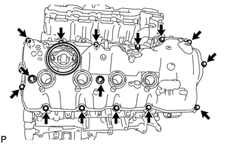
Remove the 15 bolts, 2 seal washers, cylinder head cover and gasket.
Tech Tips
Make sure the removed parts are returned to the same places they were removed from.
-
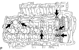
Remove the 4 gaskets and 2 O-rings from the camshaft bearing caps (No. 1, No. 3, No. 6).
-
-
REMOVE V-RIBBED BELT TENSIONER ASSEMBLY
-
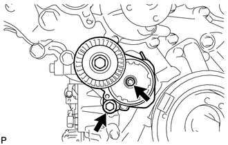
Remove the standard bolt, 6 mm hexagon wrench bolt and belt tensioner.
-
-
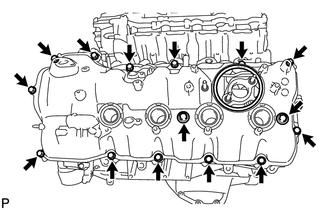
REMOVE TIMING CHAIN COVER SUB-ASSEMBLY
-
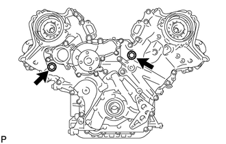
Remove the 2 plugs and 2 gaskets.
-
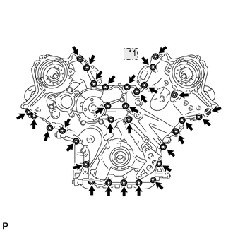
*1 Nut Remove the 30 bolts and nut shown in the illustration.
-
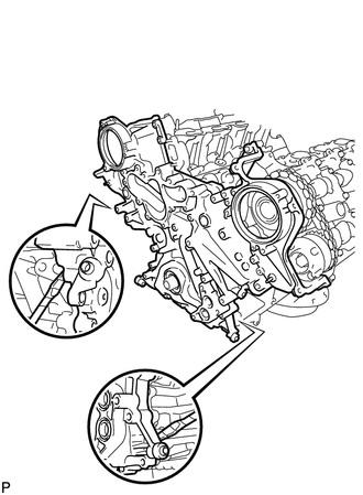
Remove the timing chain cover by prying between the timing chain cover and cylinder head and cylinder block with a screwdriver as shown in the illustration.
Note
Be careful not to damage the contact surfaces of the cylinder head, cylinder block and chain cover.
Tech Tips
Tape the screwdriver tip before use.
-
Remove the oil pump gasket from the cylinder block.
-
Remove the O-ring from the cylinder block.
-
-
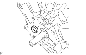
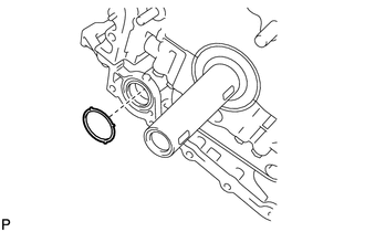
REMOVE WATER INLET PIPE
-
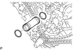
Remove the water inlet pipe.
-
Remove the 2 O-rings from the water inlet pipe.
-