ВЫПУСКНОЙ КОЛЛЕКТОР УСТАНОВКА
PROCEDURE
-
INSTALL HEATED OXYGEN SENSOR (for Bank 2 Sensor 1)
-
INSTALL HEATED OXYGEN SENSOR (for Bank 1 Sensor 1)
-
INSTALL EXHAUST MANIFOLD SUB-ASSEMBLY LH
-
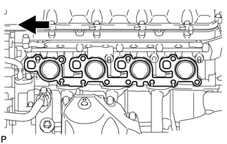
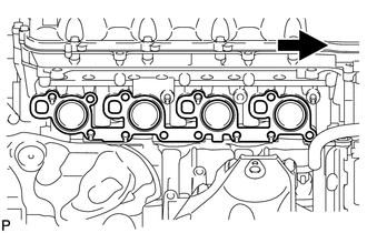
Install a new gasket as shown in the illustration.
Text in Illustration 
Front -
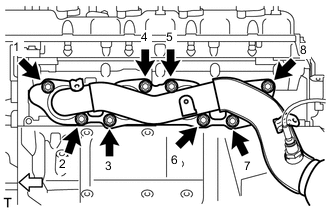
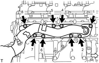
Install the exhaust manifold to the cylinder head with the new 8 nuts in the order shown in the illustration.
- Torque:
- 21 N*m { 214 kgf*cm, 15 ft.*lbf }
Text in Illustration 
Front
-
-
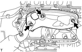
INSTALL NO. 2 EXHAUST MANIFOLD HEAT INSULATOR
-
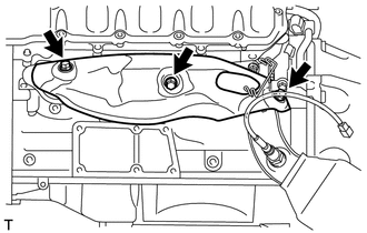
Install the heat insulator with the 3 bolts.
- Torque:
- 10 N*m { 102 kgf*cm, 7 ft.*lbf }
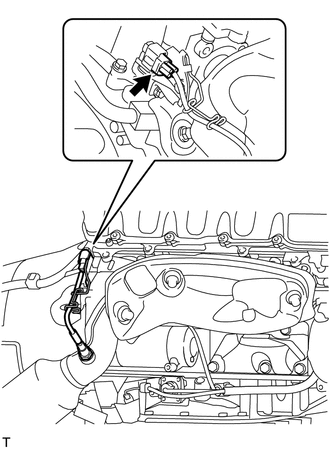
-
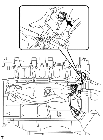
Connect the sensor connector.
-
-
INSTALL EXHAUST MANIFOLD SUB-ASSEMBLY RH
-
Install a new gasket as shown in the illustration.
Text in Illustration Front -
Install the exhaust manifold to the cylinder head with the new 8 nuts in the order shown in the illustration.
- Torque:
- 21 N*m { 214 kgf*cm, 15 ft.*lbf }
Text in Illustration Front
-
-
INSTALL NO. 1 EXHAUST MANIFOLD HEAT INSULATOR
-
Install the heat insulator with the 3 bolts.
- Torque:
- 10 N*m { 102 kgf*cm, 7 ft.*lbf }
-
Connect the sensor connector.
-
-
INSTALL ENGINE OIL LEVEL DIPSTICK GUIDE
-
INSTALL NO. 2 STEERING INTERMEDIATE SHAFT ASSEMBLY (w/ VGRS)
-
INSTALL NO. 2 STEERING INTERMEDIATE SHAFT ASSEMBLY (w/o VGRS)
-
INSTALL STEERING INTERMEDIATE SHAFT (w/o VGRS)
-
INSTALL STEERING SLIDING YOKE WITH SHAFT SUB-ASSEMBLY (w/ VGRS)
-
INSTALL STEERING SLIDING YOKE WITH SHAFT SUB-ASSEMBLY (w/o VGRS)
-
INSTALL GENERATOR ASSEMBLY
-
INSTALL V-RIBBED BELT
-
INSTALL FRONT SUSPENSION MEMBER REINFORCEMENT LH
-
INSTALL FRONT SUSPENSION MEMBER REINFORCEMENT RH
Tech Tips
Use the same procedure described for the LH side.
-
INSTALL NO. 1 EXHAUST PIPE SUPPORT BRACKET SUB-ASSEMBLY
-
INSTALL FRONT EXHAUST PIPE ASSEMBLY
-
CONNECT CABLE TO NEGATIVE BATTERY TERMINAL
Note
When disconnecting the cable, some systems need to be initialized after the cable is reconnected Click here.
-
INSTALL COWL TOP VENTILATOR LOUVER RH
-
INSPECT EXHAUST GAS LEAK
-
INSTALL FRONT SUSPENSION MEMBER PROTECTOR LOWER
-
INSTALL NO. 1 ENGINE UNDER COVER
-
INSTALL ENGINE ROOM SIDE COVER RH
-
INSTALL ENGINE ROOM SIDE COVER LH
-
INSTALL INTAKE AIR CONNECTOR PIPE
-
INSTALL NO. 1 AIR CLEANER INLET
-
INSTALL AIR CLEANER INLET COVER SUB-ASSEMBLY
-
INSTALL V-BANK COVER SUB-ASSEMBLY