INSTRUMENT PANEL SAFETY PAD INSTALLATION
CAUTION / NOTICE / HINT
Tech Tips
-
Use the same procedure for RHD and LHD vehicles.
-
The procedure listed below is for LHD vehicles.
-
A bolt without a torque specification is shown in the standard bolt chart.
PROCEDURE
-
INSTALL INSTRUMENT PANEL SAFETY PAD SUB-ASSEMBLY
-
for LHD:
-
Attach the 2 guides to install the instrument panel safety pad sub-assembly.
-
Install the 2 brackets with the 4 bolts and 2 nuts.
-
Connect the connectors and attach the clamps and claws.
-
Install the 2 passenger airbag bolts <G>.
- Torque:
- 20 N*m { 204 kgf*cm, 15 ft.*lbf }
-
Install the 6 bolts <E> and nut <F>.
-
Install the front floor carpet.
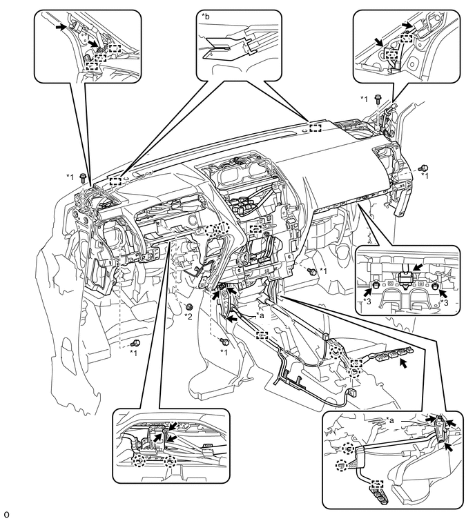
*1 Bolt <E> *2 Nut <F> *3 Bolt <G> - - *a Bracket *b Guide
-
-
for RHD:
-
Attach the 2 guides to install the instrument panel safety pad.
-
Install the 2 brackets with the 4 bolts and 2 nuts.
-
Connect the connectors and attach the clamps and claws.
-
Install the 2 passenger airbag bolts <G>.
- Torque:
- 20 N*m { 204 kgf*cm, 15 ft.*lbf }
-
Install the 6 bolts <E> and nut <F>.
-
Install the front floor carpet.
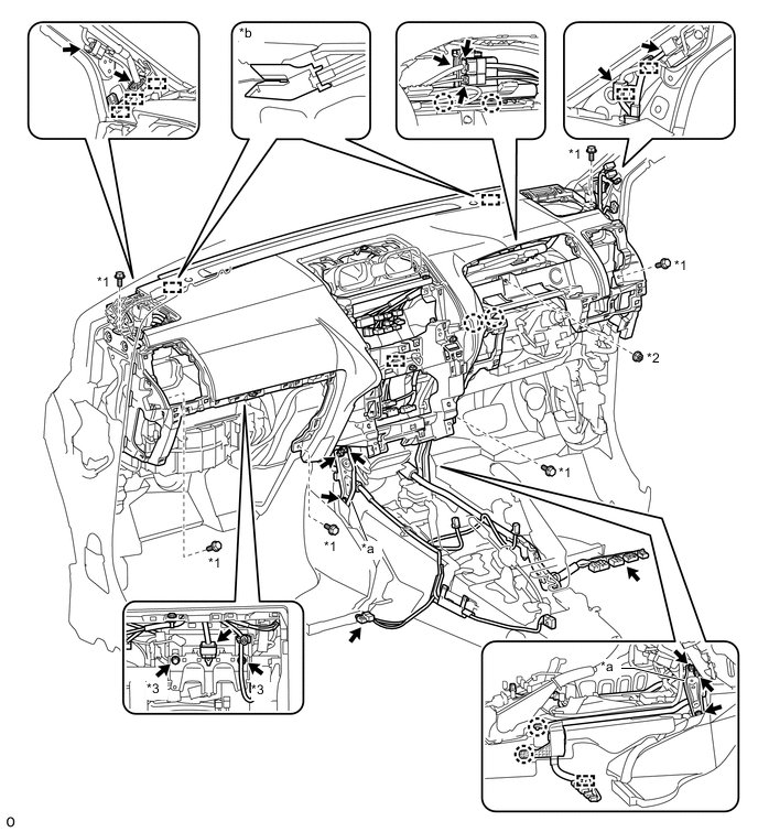
*1 Bolt <E> *2 Nut <F> *3 Bolt <G> - - *a Bracket *b Guide
-
-
-
INSTALL FRONT NO. 2 SPEAKER ASSEMBLY
-
INSTALL NO. 1 INSTRUMENT PANEL SPEAKER PANEL SUB-ASSEMBLY
-
Attach the 2 clips, claw and 2 guides to install the No. 1 instrument panel speaker panel sub-assembly.
-
-
INSTALL NO. 2 INSTRUMENT PANEL SPEAKER PANEL SUB-ASSEMBLY
Tech Tips
Use the same procedure described for the No. 1 instrument panel speaker panel sub-assembly.
-
INSTALL NO. 1 INSTRUMENT PANEL REGISTER ASSEMBLY
-
Attach the 4 clips to install the No. 1 instrument panel register assembly.
-
-
INSTALL NO. 2 INSTRUMENT PANEL REGISTER ASSEMBLY
Tech Tips
Use the same procedure described for the No. 1 instrument panel register assembly.
-
INSTALL FRONT NO. 4 SPEAKER ASSEMBLY
-
INSTALL UPPER INSTRUMENT CLUSTER FINISH PANEL
-
Attach the 8 clips and 2 guides to install the upper instrument cluster finish panel.
-
-
INSTALL LOWER CENTER INSTRUMENT CLUSTER FINISH PANEL SUB-ASSEMBLY (w/o Module Switch)
-
Attach the 3 clips and guide to install the lower center instrument cluster finish panel sub-assembly.
-
Install the 2 bolts <E>.
-
-
INSTALL CENTER CLUSTER MODULE SWITCH (w/ Module Switch)
-
INSTALL RADIO TUNER OPENING COVER (w/o Audio)
-
Install the radio tuner opening cover with the 4 bolts.
-
-
INSTALL RADIO RECEIVER ASSEMBLY (w/ Radio Receiver)
-
INSTALL NAVIGATION RECEIVER ASSEMBLY (w/ Navigation System)
-
INSTALL CENTER INSTRUMENT CLUSTER FINISH PANEL ASSEMBLY (w/o Navigation System)
-
Connect each connector.
-
Attach the 10 clips to install the center instrument cluster finish panel assembly.
-
-
INSTALL 4 WHEEL DRIVE CONTROL ECU
-
INSTALL TELEMATICS TRANSCEIVER (w/ Telematics Transceiver)
-
INSTALL DOUBLE LOCK DOOR CONTROL RELAY ASSEMBLY (w/ Telematics Transceiver, Double Door Lock)
-
INSTALL GLOVE COMPARTMENT DOOR ASSEMBLY
*1 Bolt *2 Screw
-
Connect each connector.
-
Attach the 5 clips and claw to install the glove compartment door assembly.
-
Install the 2 bolts <C> and 2 screws <A> or <B>.
-
-
INSTALL INSTRUMENT PANEL ORNAMENT
-
Attach the 5 clips to install the instrument panel ornament.
-
-
INSTALL INSTRUMENT SIDE PANEL RH
-
Connect the connector.
-
Attach the 5 clips, claw and 3 guides to install the instrument side panel RH.
-
-
INSTALL COMBINATION METER ASSEMBLY
-
INSTALL INSTRUMENT CLUSTER FINISH PANEL SUB-ASSEMBLY
-
except 5L-E:
-
Connect the connector.
-
Attach the 4 claws, 2 clips and 2 guides to install the instrument cluster finish panel sub-assembly.
-
-
for 5L-E:
-
Connect the connector.
-
Attach the 4 claws, 2 clips and 2 guides to install the instrument cluster finish panel sub-assembly.
-
-
-
INSTALL LOWER NO. 1 INSTRUMENT PANEL AIRBAG ASSEMBLY
-
INSTALL LOWER INSTRUMENT PANEL FINISH PANEL SUB-ASSEMBLY
-
Connect each connector and each cable.
-
w/o Knee Airbag:
-
Attach the 7 clips to install the lower instrument panel finish panel sub-assembly.
-
-
w/ Knee Airbag:
-
Attach the 14 clips to install the lower instrument panel finish panel sub-assembly.
-
-
Install the 2 bolts <C>.
-
Attach the 2 claws to close the cover.
-
-
INSTALL LOWER INSTRUMENT PANEL FINISH PANEL ASSEMBLY
-
Connect each connector.
-
Attach the 4 clips to install the lower instrument panel finish panel assembly.
-
-
INSTALL INSTRUMENT PANEL FINISH PLATE GARNISH (for RHD)
-
Connect each connector.
-
Attach the 4 clips to install the instrument panel finish plate garnish.
-
-
INSTALL INSTRUMENT CLUSTER FINISH PANEL ORNAMENT (for LHD)
-
Attach the 3 clips to install the instrument cluster finish panel ornament.
-
-
INSTALL INSTRUMENT SIDE PANEL LH
-
Attach the 5 clips, claw and 3 guides to install the instrument side panel LH.
-
-
INSTALL FRONT NO. 3 SPEAKER ASSEMBLY
-
INSTALL FRONT PILLAR GARNISH LH
-
INSTALL FRONT PILLAR GARNISH RH
Tech Tips
Use the same procedure described for the LH side.
-
INSTALL NO. 1 ASSIST GRIP
-
INSTALL FRONT NO. 1 ASSIST GRIP PLUG LH
-
INSTALL FRONT NO. 1 ASSIST GRIP PLUG RH
Tech Tips
Use the same procedure described for the LH side.
-
INSTALL FRONT DOOR OPENING TRIM WEATHERSTRIP LH
-
INSTALL FRONT DOOR OPENING TRIM WEATHERSTRIP RH
Tech Tips
Use the same procedure described for the LH side.
-
INSTALL COWL SIDE TRIM BOARD LH
-
INSTALL COWL SIDE TRIM BOARD RH
Tech Tips
Use the same procedure described for the LH side.
-
INSTALL DOOR SCUFF PLATE ASSEMBLY LH
-
INSTALL DOOR SCUFF PLATE ASSEMBLY RH
Tech Tips
Use the same procedure described for the LH side.
-
INSTALL REAR CONSOLE BOX ASSEMBLY
-
for Automatic Transmission:
-
for Manual Transmission:
-
w/ Refrigerated Cool Box:
-
for Bench Seat Type:
-
-
INSTALL FRONT FLOOR FOOTREST
-
for LHD:
-
for RHD:
-
-
INSTALL FRONT SEAT ASSEMBLY LH
-
for Manual Seat:
-
for Power Seat:
-
-
INSTALL FRONT SEAT ASSEMBLY RH
-
for Manual Seat:
Tech Tips
Use the same procedure described for the LH side.
-
for Power Seat:
Tech Tips
Use the same procedure described for the LH side.
-
for Walk in Seat Type:
-
-
INSTALL HEADLIGHT DIMMER SWITCH ASSEMBLY
-
CONNECT CABLE TO NEGATIVE BATTERY TERMINAL
Note
-
Reset the AUTO TILT AWAY function setting to the previous condition by changing the customize parameter.
-
When disconnecting the cable, some systems need to be initialized after the cable is reconnected.
-
-
CHECK SRS WARNING LIGHT