CAN COMMUNICATION SYSTEM(for RHD with Entry and Start System), Diagnostic DTC:U1002
| DTC Code | DTC Name |
|---|---|
| U1002 | Lost Communication with Gateway Module (Power Management1) |
DESCRIPTION
-
The power management control ECU stores this DTC when no signals can be received from the ECUs that have been memorized as those connected to the V2 bus.
-
When the power management control ECU receives a response signal from the ECUs connected to the V2 bus, the power management control ECU recognizes and memorizes that the ECU is connected to the V2 bus. Based on this memorized data, the power management control ECU monitors for malfunctions in the ECUs connected to the V2 bus when communicating with those ECUs. If the power management control ECU cannot receive response signals from the ECUs that have been memorized as those connected to the V2 bus, the power management control ECU determines that a malfunction exists.
-
If 2 or more DTCs are output during the DTC check, one side of the CAN branch wire may be open (one side of the CANH [CAN branch wire]/CANL [CAN branch wire] of the ECU and/or sensor is open).
| DTC Code | DTC Detection Condition | Trouble Area |
|---|---|---|
| U1002 | Lost communication with the gateway module (Power Management1). |
|
-
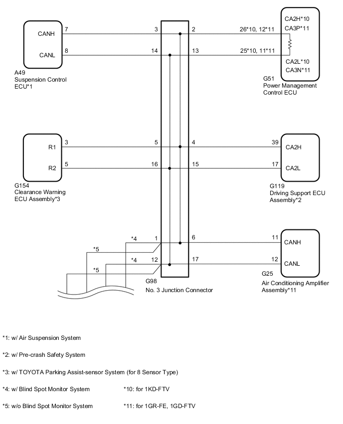
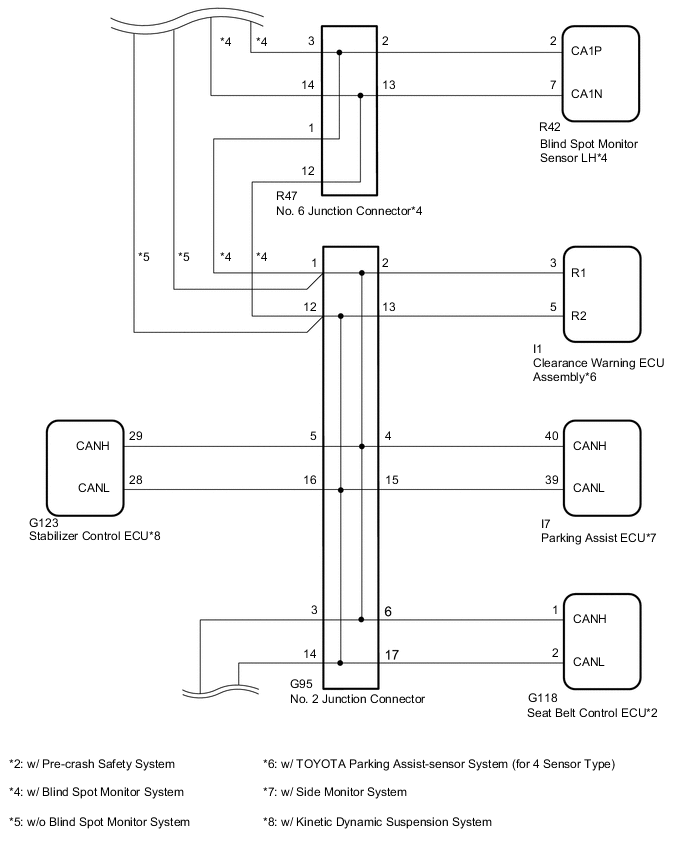
*1: w/ Side Monitor System
-
*2: w/ TOYOTA Parking Assist-sensor System
-
*3: w/ Pre-crash Safety System
-
*4: w/ Kinetic Dynamic Suspension System
-
*5: w/ Blind Spot Monitor System
-
*6: w/ Air Suspension System
-
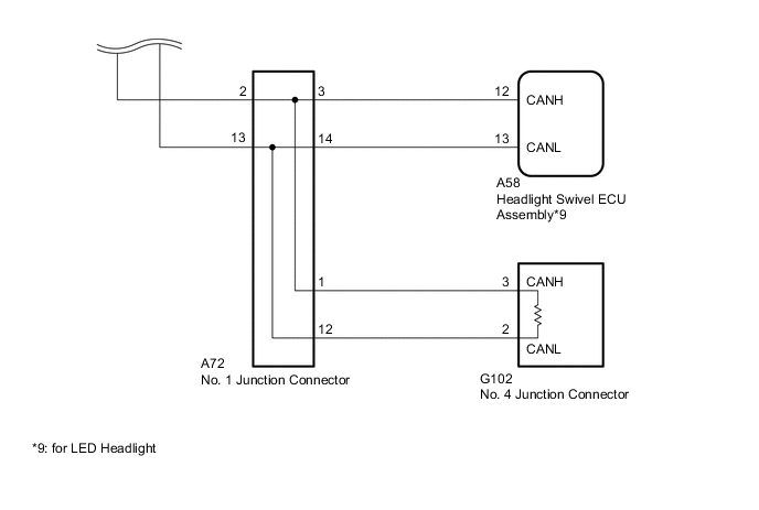
*7: for LED Headlight
-
*8: for 1GR-FE, 1GD-FTV
WIRING DIAGRAM
CAUTION / NOTICE / HINT
Tech Tips
Operating the engine switch, any switches or any doors triggers related ECU and sensor communication with the CAN, which causes resistance variation.
PROCEDURE
-
DISCONNECT CABLE FROM NEGATIVE BATTERY TERMINAL
-
Disconnect the cable from the negative (-) battery terminal before measuring the resistances of the CAN main wire and the CAN branch wire.
CAUTION:
Wait at least 90 seconds after disconnecting the cable from the negative (-) battery terminal to disable the airbag system.
Note
-
After turning the engine switch off, waiting time may be required before disconnecting the cable from the battery terminal. Therefore, make sure to read the disconnecting the cable from the battery terminal notice before proceeding with work Click here.
-
When disconnecting the cable, some systems need to be initialized after the cable is reconnected Click here.
-
NEXT 
-
-
CHECK CAN BUS WIRE (CAN MAIN WIRE FOR DISCONNECTION, BUS LINE FOR SHORT CIRCUIT)
-

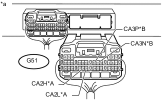
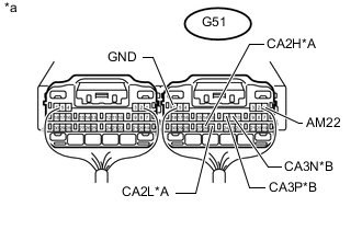
Text in Illustration *A for 1KD-FTV *B for 1GR-FE, 1GD-FTV *a Component with harness connector
(Power Management Control ECU)
Measure the resistance according to the value(s) in the table below.
Standard Resistance for 1KD-FTV Tester Connection Switch Condition Specified Condition Resistance: Malfunction G51-26 (CA2H) - G51-25 (CA2L) Engine switch off 54 to 69 Ω Below 53 Ω: Short in line G51-26 (CA2H) - G51-25 (CA2L) Engine switch off 54 to 69 Ω Higher than 70 Ω: Open in CAN main bus line G51-26 (CA2H) - G51-1 (AM22) Engine switch off 6 kΩ or higher Below 6 kΩ: +B short G51-25 (CA2L) - G51-1 (AM22) Engine switch off 6 kΩ or higher Below 6 kΩ: +B short G51-26 (CA2H) - G51-6 (GND) Engine switch off 200 Ω or higher Below 200 Ω: Ground short G51-25 (CA2L) - G51-6 (GND) Engine switch off 200 Ω or higher Below 200 Ω: Ground short for 1GR-FE, 1GD-FTV Tester Connection Switch Condition Specified Condition Resistance: Malfunction G51-12 (CA3P) - G51-11 (CA3N) Engine switch off 54 to 69 Ω Below 53 Ω: Short in line G51-12 (CA3P) - G51-11 (CA3N) Engine switch off 54 to 69 Ω Higher than 70 Ω: Open in CAN main bus line G51-12 (CA3P) - G51-1 (AM22) Engine switch off 6 kΩ or higher Below 6 kΩ: +B short G51-11 (CA3N) - G51-1 (AM22) Engine switch off 6 kΩ or higher Below 6 kΩ: +B short G51-12 (CA3P) - G51-6 (GND) Engine switch off 200 Ω or higher Below 200 Ω: Ground short G51-11 (CA3N) - G51-6 (GND) Engine switch off 200 Ω or higher Below 200 Ω: Ground short Result Result Proceed to NG
-
Open in CAN main bus line
A NG
-
Short in line
-
+B short
-
Ground short
B OK C -
B 
CHECK FOR SHORT IN CAN BUS WIRES (NO. 1 JUNCTION CONNECTOR SIDE) Click here
C
CHECK HARNESS AND CONNECTOR (POWER MANAGEMENT CONTROL ECU - BATTERY AND BODY GROUND) Click here
A
-
-
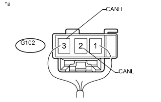
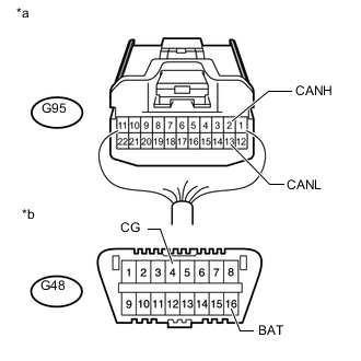
CHECK FOR OPEN IN CAN BUS MAIN WIRE (NO. 3 JUNCTION CONNECTOR - POWER MANAGEMENT CONTROL ECU)
-
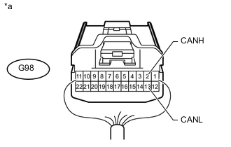
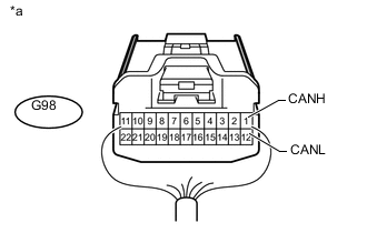
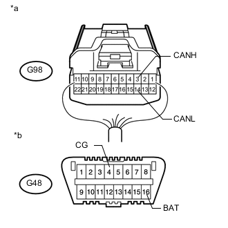
Text in Illustration *a Rear view of wire harness connector
(to No. 3 Junction Connector)
Disconnect the G98 No. 3 junction connector.
-
Measure the resistance according to the value(s) in the table below.
Standard Resistance Tester Connection Switch Condition Specified Condition G98-2 (CANH) - G98-13 (CANL) Engine switch off 108 to 132 Ω
NG
CONNECT CONNECTOR Click here
OK
-
-
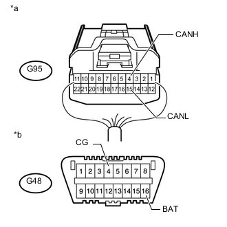
CHECK FOR OPEN IN CAN BUS MAIN WIRE (NO. 3 JUNCTION CONNECTOR - NO. 4 JUNCTION CONNECTOR)
-
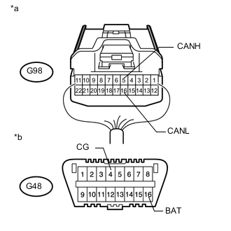
Text in Illustration *a Rear view of wire harness connector
(to No. 3 Junction Connector)
Measure the resistance according to the value(s) in the table below.
Standard Resistance Tester Connection Switch Condition Specified Condition G98-1 (CANH) - G98-12 (CANL) Engine switch off 108 to 132 Ω Result Result Proceed to OK A NG (w/ Blind Spot Monitor System) B NG (w/o Blind Spot Monitor System) C
A 
REPLACE NO. 3 JUNCTION CONNECTOR
B
CONNECT CONNECTOR Click here
C
CONNECT CONNECTOR Click here
-
-
CONNECT CONNECTOR
-
Reconnect the G98 No. 3 junction connector.
NEXT
-
-
CHECK FOR OPEN IN CAN BUS MAIN WIRE (POWER MANAGEMENT CONTROL ECU - NO. 3 JUNCTION CONNECTOR)
-
Text in Illustration *A for 1KD-FTV *B for 1GR-FE, 1GD-FTV *a Rear view of wire harness connector
(to Power Management Control ECU)
Disconnect the G51 power management control ECU connector.
-
Measure the resistance according to the value(s) in the table below.
Standard Resistance for 1KD-FTV Tester Connection Switch Condition Specified Condition G51-26 (CA2H) - G51-25 (CA2L) Engine switch off 108 to 132 Ω for 1GR-FE, 1GD-FTV Tester Connection Switch Condition Specified Condition G51-12 (CA3P) - G51-25 (CA3N) Engine switch off 108 to 132 Ω
OK
REPLACE POWER MANAGEMENT CONTROL ECU Click here
NG
REPAIR OR REPLACE CAN MAIN WIRE CONNECTED TO POWER MANAGEMENT CONTROL ECU (POWER MANAGEMENT CONTROL ECU - NO. 3 JUNCTION CONNECTOR)
-
-
CONNECT CONNECTOR
-
Reconnect the G98 No. 3 junction connector.
NEXT
-
-
CHECK FOR OPEN IN CAN BUS MAIN WIRE (NO. 6 JUNCTION CONNECTOR - NO. 4 JUNCTION CONNECTOR)
-
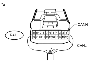
Text in Illustration *a Rear view of wire harness connector
(to No. 6 Junction Connector)
Disconnect the R47 No. 6 junction connector.
-
Measure the resistance according to the value(s) in the table below.
Standard Resistance Tester Connection Switch Condition Specified Condition R47-1 (CANH) - R47-12 (CANL) Engine switch off 108 to 132 Ω
NG
CONNECT CONNECTOR Click here
OK
-
-
CHECK FOR OPEN IN CAN BUS MAIN WIRE (NO. 6 JUNCTION CONNECTOR - NO. 3 JUNCTION CONNECTOR)
-
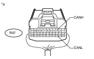
Text in Illustration *a Rear view of wire harness connector
(to No. 6 Junction Connector)
Measure the resistance according to the value(s) in the table below.
Standard Resistance Tester Connection Switch Condition Specified Condition R47-3 (CANH) - R47-14 (CANL) Engine switch off 108 to 132 Ω
OK
REPLACE NO. 6 JUNCTION CONNECTOR
NG
REPAIR OR REPLACE CAN MAIN WIRE OR CONNECTOR (NO. 6 JUNCTION CONNECTOR - NO. 3 JUNCTION CONNECTOR)
-
-
CONNECT CONNECTOR
-
Reconnect the R47 No. 6 junction connector.
NEXT
-
-
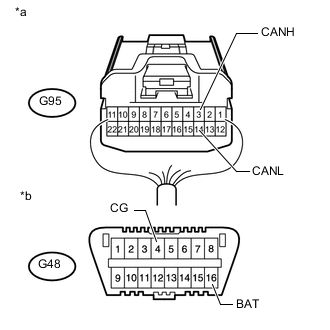
CHECK FOR OPEN IN CAN BUS MAIN WIRE (NO. 2 JUNCTION CONNECTOR - NO. 4 JUNCTION CONNECTOR)
-
Text in Illustration *a Rear view of wire harness connector
(to No. 2 Junction Connector)
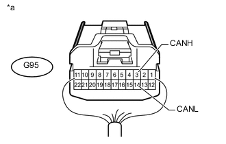
Disconnect the G95 No. 2 junction connector.
-
Measure the resistance according to the value(s) in the table below.
Standard Resistance Tester Connection Switch Condition Specified Condition G95-3 (CANH) - G95-14 (CANL) Engine switch off 108 to 132 Ω
NG
CONNECT CONNECTOR Click here
OK
-
-
CHECK FOR OPEN IN CAN BUS MAIN WIRE (NO. 2 JUNCTION CONNECTOR - NO. 6 JUNCTION CONNECTOR)
-
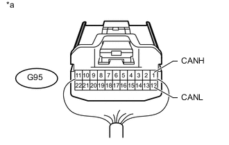
Text in Illustration *a Rear view of wire harness connector
(to No. 2 Junction Connector)
Measure the resistance according to the value(s) in the table below.
Standard Resistance Tester Connection Switch Condition Specified Condition G95-1 (CANH) - G95-12 (CANL) Engine switch off 108 to 132 Ω
OK
REPLACE NO. 2 JUNCTION CONNECTOR
NG
REPAIR OR REPLACE CAN MAIN WIRE OR CONNECTOR (NO. 2 JUNCTION CONNECTOR - NO. 6 JUNCTION CONNECTOR)
-
-
CONNECT CONNECTOR
-
Reconnect the G98 No. 3 junction connector.
NEXT
-
-
CHECK FOR OPEN IN CAN BUS MAIN WIRE (NO. 2 JUNCTION CONNECTOR - NO. 4 JUNCTION CONNECTOR)
-

Text in Illustration *a Rear view of wire harness connector
(to No. 2 Junction Connector)
Disconnect the G95 No. 2 junction connector.
-
Measure the resistance according to the value(s) in the table below.
Standard Resistance Tester Connection Switch Condition Specified Condition G95-3 (CANH) - G95-14 (CANL) Engine switch off 108 to 132 Ω
NG
CONNECT CONNECTOR Click here
OK
-
-
CHECK FOR OPEN IN CAN BUS MAIN WIRE (NO. 2 JUNCTION CONNECTOR - NO. 3 JUNCTION CONNECTOR)
-

Text in Illustration *a Rear view of wire harness connector
(to No. 2 Junction Connector)
Measure the resistance according to the value(s) in the table below.
Standard Resistance Tester Connection Switch Condition Specified Condition G95-1 (CANH) - G95-12 (CANL) Engine switch off 108 to 132 Ω
OK
REPLACE NO. 2 JUNCTION CONNECTOR
NG
REPAIR OR REPLACE CAN MAIN WIRE OR CONNECTOR (NO. 2 JUNCTION CONNECTOR - NO. 3 JUNCTION CONNECTOR)
-
-
CONNECT CONNECTOR
-
Reconnect the G95 No. 2 junction connector.
NEXT
-
-
CHECK FOR OPEN IN CAN BUS MAIN WIRE (NO. 1 JUNCTION CONNECTOR - NO. 4 JUNCTION CONNECTOR)
-
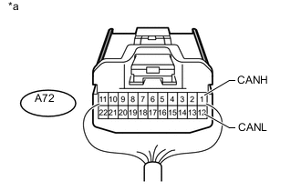
Text in Illustration *a Rear view of wire harness connector
(to No. 1 Junction Connector)
Disconnect the A72 No. 1 junction connector.
-
Measure the resistance according to the value(s) in the table below.
Standard Resistance Tester Connection Switch Condition Specified Condition A72-1 (CANH) - A72-12 (CANL) Engine switch off 108 to 132 Ω
NG
CONNECT CONNECTOR Click here
OK
-
-
CHECK FOR OPEN IN CAN BUS MAIN WIRE (NO. 1 JUNCTION CONNECTOR - NO. 2 JUNCTION CONNECTOR)
-
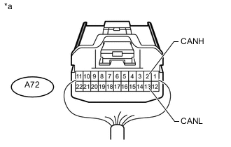
Text in Illustration *a Rear view of wire harness connector
(to No. 1 Junction Connector)
Measure the resistance according to the value(s) in the table below.
Standard Resistance Tester Connection Switch Condition Specified Condition A72-2 (CANH) - A72-13 (CANL) Engine switch off 108 to 132 Ω
OK
REPLACE NO. 1 JUNCTION CONNECTOR
NG
REPAIR OR REPLACE CAN MAIN WIRE OR CONNECTOR (NO. 1 JUNCTION CONNECTOR - NO. 2 JUNCTION CONNECTOR)
-
-
CONNECT CONNECTOR
-
Reconnect the A72 No. 1 junction connector.
NEXT
-
-
CHECK FOR OPEN IN CAN BUS MAIN WIRE (NO. 4 JUNCTION CONNECTOR - NO. 1 JUNCTION CONNECTOR)
-
Text in Illustration *a Rear view of wire harness connector
(to No. 4 Junction Connector)
Disconnect the G102 No. 4 junction connector.
-
Measure the resistance according to the value(s) in the table below.
Standard Resistance Tester Connection Switch Condition Specified Condition G102-3 (CANH) - G102-2 (CANL) Engine switch off 108 to 132 Ω
OK
REPLACE NO. 4 JUNCTION CONNECTOR
NG
REPAIR OR REPLACE CAN MAIN WIRE OR CONNECTOR (NO. 4 JUNCTION CONNECTOR - NO. 1 JUNCTION CONNECTOR)
-
-
CHECK FOR SHORT IN CAN BUS WIRES (NO. 1 JUNCTION CONNECTOR SIDE)
-

Text in Illustration *A for 1KD-FTV *B for 1GR-FE, 1GD-FTV *a Component with harness connector
(Power Management Control ECU)
Disconnect the A72 No. 1 junction connector.
-
Measure the resistance according to the value(s) in the table below.
Standard Resistance for 1KD-FTV Tester Connection Switch Condition Specified Condition G51-26 (CA2H) - G51-25 (CA2L) Engine switch off 108 to 132 Ω G51-26 (CA2H) - G51-6 (GND) Engine switch off 200 Ω or higher G51-25 (CA2L) - G51-6 (GND) Engine switch off 200 Ω or higher G51-26 (CA2H) - G51-1 (AM22) Engine switch off 6 kΩ or higher G51-25 (CA2L) - G51-1 (AM22) Engine switch off 6 kΩ or higher for 1GR-FE, 1GD-FTV Tester Connection Switch Condition Specified Condition G51-12 (CA3P) - G51-11 (CA3N) Engine switch off 108 to 132 Ω G51-12 (CA3P) - G51-6 (GND) Engine switch off 200 Ω or higher G51-11 (CA3N) - G51-6 (GND) Engine switch off 200 Ω or higher G51-12 (CA3P) - G51-1 (AM22) Engine switch off 6 kΩ or higher G51-11 (CA3N) - G51-1 (AM22) Engine switch off 6 kΩ or higher
NG
CONNECT CONNECTOR Click here
OK
-
-
CHECK FOR SHORT IN CAN BUS WIRES (NO. 1 JUNCTION CONNECTOR - HEADLIGHT SWIVEL ECU ASSEMBLY)
Note
For vehicles with a halogen headlight, go to "Check for Short in CAN Bus Wires (No. 1 Junction Connector - No. 4 Junction Connector)".
-
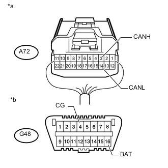
Text in Illustration *a Rear view of wire harness connector
(to No. 1 Junction Connector)
*b Front view of DLC3 Measure the resistance according to the value(s) in the table below.
Standard Resistance Tester Connection Switch Condition Specified Condition A72-3 (CANH) - A72-14 (CANL) Engine switch off 200 Ω or higher A72-3 (CANH) - G48-4 (CG) Engine switch off 200 Ω or higher A72-14 (CANL) - G48-4 (CG) Engine switch off 200 Ω or higher A72-3 (CANH) - G48-16 (BAT) Engine switch off 6 kΩ or higher A72-14 (CANL) - G48-16 (BAT) Engine switch off 6 kΩ or higher
NG
CONNECT CONNECTOR Click here
OK
-
-
CHECK FOR SHORT IN CAN BUS WIRES (NO. 1 JUNCTION CONNECTOR - NO. 4 JUNCTION CONNECTOR)
-
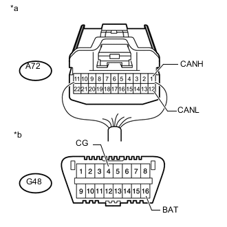
Text in Illustration *a Rear view of wire harness connector
(to No. 1 Junction Connector)
*b Front view of DLC3 Measure the resistance according to the value(s) in the table below.
Standard Resistance Tester Connection Switch Condition Specified Condition A72-1 (CANH) - A72-12 (CANL) Engine switch off 108 to 132 Ω A72-1 (CANH) - G48-4 (CG) Engine switch off 200 Ω or higher A72-12 (CANL) - G48-4 (CG) Engine switch off 200 Ω or higher A72-1 (CANH) - G48-16 (BAT) Engine switch off 6 kΩ or higher A72-12 (CANL) - G48-16 (BAT) Engine switch off 6 kΩ or higher
OK
REPLACE NO. 1 JUNCTION CONNECTOR
NG
CONNECT CONNECTOR Click here
-
-
CONNECT CONNECTOR
-
Reconnect the A72 No. 1 junction connector.
NEXT
-
-
CHECK FOR SHORT IN CAN BUS WIRES (HEADLIGHT SWIVEL ECU ASSEMBLY)
-

Text in Illustration *a Front view of wire harness connector
(to Headlight Swivel ECU Assembly)
*b Front view of DLC3 Disconnect the A58 headlight swivel ECU assembly connector.
-
Measure the resistance according to the value(s) in the table below.
Standard Resistance Tester Connection Switch Condition Specified Condition A58-12 (CANH) - A58-13 (CANL) Engine switch off 54 to 69 Ω A58-12 (CANH) - G48-4 (CG) Engine switch off 200 Ω or higher A58-13 (CANL) - G48-4 (CG) Engine switch off 200 Ω or higher A58-12 (CANH) - G48-16 (BAT) Engine switch off 6 kΩ or higher A58-13 (CANL) - G48-16 (BAT) Engine switch off 6 kΩ or higher
OK
REPLACE HEADLIGHT SWIVEL ECU ASSEMBLY Click here
NG
REPAIR OR REPLACE CAN BRANCH WIRE CONNECTED TO HEADLIGHT SWIVEL ECU ASSEMBLY (CANH, CANL)
-
-
CONNECT CONNECTOR
-
Reconnect the A72 No. 1 junction connector.
NEXT
-
-
CHECK FOR SHORT IN CAN BUS WIRES (NO. 4 JUNCTION CONNECTOR)
-
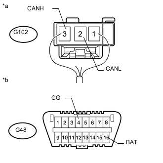
Text in Illustration *a Rear view of wire harness connector
(to No. 4 Junction Connector)
*b Front view of DLC3 Disconnect the G102 No. 4 junction connector.
-
Measure the resistance according to the value(s) in the table below.
Standard Resistance Tester Connection Switch Condition Specified Condition G102-3 (CANH) - G102-2 (CANL) Engine switch off 108 to 132 Ω G102-3 (CANH) - G48-4 (CG) Engine switch off 200 Ω or higher G102-2 (CANL) - G48-4 (CG) Engine switch off 200 Ω or higher G102-3 (CANH) - G48-16 (BAT) Engine switch off 6 kΩ or higher G102-2 (CANL) - G48-16 (BAT) Engine switch off 6 kΩ or higher
OK
REPLACE NO. 4 JUNCTION CONNECTOR
NG
REPAIR OR REPLACE CAN MAIN WIRE OR CONNECTOR (NO. 4 JUNCTION CONNECTOR - NO. 1 JUNCTION CONNECTOR)
-
-
CONNECT CONNECTOR
-
Reconnect the A72 No. 1 junction connector.
NEXT
-
-
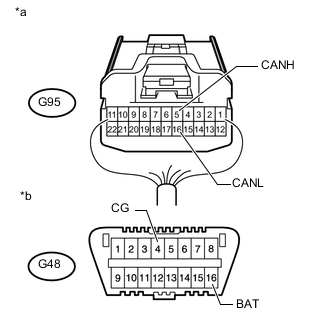
CHECK FOR SHORT IN CAN BUS WIRES (NO. 2 JUNCTION CONNECTOR - NO. 1 JUNCTION CONNECTOR)
-
Text in Illustration *a Rear view of wire harness connector
(to No. 2 Junction Connector)
*b Front view of DLC3 Disconnect the G95 No. 2 junction connector.
-
Measure the resistance according to the value(s) in the table below.
Standard Resistance Tester Connection Switch Condition Specified Condition G95-3 (CANH) - G95-14 (CANL) Engine switch off 108 to 132 Ω G95-3 (CANH) - G48-4 (CG) Engine switch off 200 Ω or higher G95-14 (CANL) - G48-4 (CG) Engine switch off 200 Ω or higher G95-3 (CANH) - G48-16 (BAT) Engine switch off 6 kΩ or higher G95-14 (CANL) - G48-16 (BAT) Engine switch off 6 kΩ or higher
NG
REPAIR OR REPLACE CAN MAIN WIRE OR CONNECTOR (NO. 2 JUNCTION CONNECTOR - NO. 1 JUNCTION CONNECTOR)
OK
-
-
CHECK FOR SHORT IN CAN BUS WIRES (NO. 2 JUNCTION CONNECTOR SIDE)
-
Text in Illustration *A for 1KD-FTV *B for 1GR-FE, 1GD-FTV *a Component with harness connector
(Power Management Control ECU)
Measure the resistance according to the value(s) in the table below.
Standard Resistance for 1KD-FTV Tester Connection Switch Condition Specified Condition G51-26 (CA2H) - G51-25 (CA2L) Engine switch off 108 to 132 Ω G51-26 (CA2H) - G51-6 (GND) Engine switch off 200 Ω or higher G51-25 (CA2L) - G51-6 (GND) Engine switch off 200 Ω or higher G51-26 (CA2H) - G51-1 (AM22) Engine switch off 6 kΩ or higher G51-25 (CA2L) - G51-1 (AM22) Engine switch off 6 kΩ or higher for 1GR-FE, 1GD-FTV Tester Connection Switch Condition Specified Condition G51-12 (CA3P) - G51-11 (CA3N) Engine switch off 108 to 132 Ω G51-12 (CA3P) - G51-6 (GND) Engine switch off 200 Ω or higher G51-11 (CA3N) - G51-6 (GND) Engine switch off 200 Ω or higher G51-12 (CA3P) - G51-1 (AM22) Engine switch off 6 kΩ or higher G51-11 (CA3N) - G51-1 (AM22) Engine switch off 6 kΩ or higher Result Result Proceed to OK A NG (w/ Blind Spot Monitor System) B NG (w/o Blind Spot Monitor System) C
B
CONNECT CONNECTOR Click here
C
CONNECT CONNECTOR Click here
A
-
-
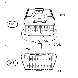
CHECK FOR SHORT IN CAN BUS WIRES (NO. 2 JUNCTION CONNECTOR - CLEARANCE WARNING ECU ASSEMBLY)
Note
For vehicles without a TOYOTA parking assist-sensor system (for 4 sensor type), go to "Check for Short in CAN Bus Wires (No. 2 Junction Connector - Parking Assist ECU)".
-
Text in Illustration *a Rear view of wire harness connector
(to No. 2 Junction Connector)
*b Front view of DLC3 Measure the resistance according to the value(s) in the table below.
Standard Resistance Tester Connection Switch Condition Specified Condition G95-2 (CANH) - G95-13 (CANL) Engine switch off 200 Ω or higher G95-2 (CANH) - G48-4 (CG) Engine switch off 200 Ω or higher G95-13 (CANL) - G48-4 (CG) Engine switch off 200 Ω or higher G95-2 (CANH) - G48-16 (BAT) Engine switch off 6 kΩ or higher G95-13 (CANL) - G48-16 (BAT) Engine switch off 6 kΩ or higher
NG
CONNECT CONNECTOR Click here
OK
-
-
CHECK FOR SHORT IN CAN BUS WIRES (NO. 2 JUNCTION CONNECTOR - PARKING ASSIST ECU)
Note
For vehicles without a side monitor system, go to "Check for Short in CAN Bus Wires (No. 2 Junction Connector - Stabilizer Control ECU)".
-
Text in Illustration *a Rear view of wire harness connector
(to No. 2 Junction Connector)
*b Front view of DLC3 Measure the resistance according to the value(s) in the table below.
Standard Resistance Tester Connection Switch Condition Specified Condition G95-4 (CANH) - G95-15 (CANL) Engine switch off 200 Ω or higher G95-4 (CANH) - G48-4 (CG) Engine switch off 200 Ω or higher G95-15 (CANL) - G48-4 (CG) Engine switch off 200 Ω or higher G95-4 (CANH) - G48-16 (BAT) Engine switch off 6 kΩ or higher G95-15 (CANL) - G48-16 (BAT) Engine switch off 6 kΩ or higher
NG
CONNECT CONNECTOR Click here
OK
-
-
CHECK FOR SHORT IN CAN BUS WIRES (NO. 2 JUNCTION CONNECTOR - STABILIZER CONTROL ECU)
Note
For vehicles without a kinetic dynamic suspension system, go to "Check for Short in CAN Bus Wires (No. 2 Junction Connector - Seat Belt Control ECU)".
-
Text in Illustration *a Rear view of wire harness connector
(to No. 2 Junction Connector)
*b Front view of DLC3 Measure the resistance according to the value(s) in the table below.
Standard Resistance Tester Connection Switch Condition Specified Condition G95-5 (CANH) - G95-16 (CANL) Engine switch off 200 Ω or higher G95-5 (CANH) - G48-4 (CG) Engine switch off 200 Ω or higher G95-16 (CANL) - G48-4 (CG) Engine switch off 200 Ω or higher G95-5 (CANH) - G48-16 (BAT) Engine switch off 6 kΩ or higher G95-16 (CANL) - G48-16 (BAT) Engine switch off 6 kΩ or higher
NG
CONNECT CONNECTOR Click here
OK
-
-
CHECK FOR SHORT IN CAN BUS WIRES (NO. 2 JUNCTION CONNECTOR - SEAT BELT CONTROL ECU)
Note
For vehicles without a pre-crash safety system, replace No. 2 junction connector.
-
Text in Illustration *a Rear view of wire harness connector
(to No. 2 Junction Connector)
*b Front view of DLC3 Measure the resistance according to the value(s) in the table below.
Standard Resistance Tester Connection Switch Condition Specified Condition G95-6 (CANH) - G95-17 (CANL) Engine switch off 200 Ω or higher G95-6 (CANH) - G48-4 (CG) Engine switch off 200 Ω or higher G95-17 (CANL) - G48-4 (CG) Engine switch off 200 Ω or higher G95-6 (CANH) - G48-16 (BAT) Engine switch off 6 kΩ or higher G95-17 (CANL) - G48-16 (BAT) Engine switch off 6 kΩ or higher
OK
REPLACE NO. 2 JUNCTION CONNECTOR
NG
CONNECT CONNECTOR Click here
-
-
CONNECT CONNECTOR
-
Reconnect the G95 No. 2 junction connector.
NEXT
-
-
CHECK FOR SHORT IN CAN BUS WIRES (CLEARANCE WARNING ECU ASSEMBLY)
-
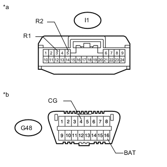
Text in Illustration *a Front view of wire harness connector
(to Clearance Warning ECU Assembly)
*b Front view of DLC3 Disconnect the I1 clearance warning ECU assembly connector.
-
Measure the resistance according to the value(s) in the table below.
Standard Resistance Tester Connection Switch Condition Specified Condition I1-3 (R1) - I1-5 (R2) Engine switch off 54 to 69 Ω I1-3 (R1) - G48-4 (CG) Engine switch off 200 Ω or higher I1-5 (R2) - G48-4 (CG) Engine switch off 200 Ω or higher I1-3 (R1) - G48-16 (BAT) Engine switch off 6 kΩ or higher I1-5 (R2) - G48-16 (BAT) Engine switch off 6 kΩ or higher
OK
REPLACE CLEARANCE WARNING ECU ASSEMBLY Click here
NG
REPAIR OR REPLACE CAN BRANCH WIRE CONNECTED TO CLEARANCE WARNING ECU ASSEMBLY (R1, R2)
-
-
CONNECT CONNECTOR
-
Reconnect the G95 No. 2 junction connector.
NEXT
-
-
CHECK FOR SHORT IN CAN BUS WIRES (PARKING ASSIST ECU)
-
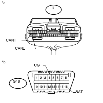
Text in Illustration *a Rear view of wire harness connector
(to Parking Assist ECU)
*b Front view of DLC3 Disconnect the I7 parking assist ECU connector.
-
Measure the resistance according to the value(s) in the table below.
Standard Resistance Tester Connection Switch Condition Specified Condition I7-40 (CANH) - I7-39 (CANL) Engine switch off 54 to 69 Ω I7-40 (CANH) - G48-4 (CG) Engine switch off 200 Ω or higher I7-39 (CANL) - G48-4 (CG) Engine switch off 200 Ω or higher I7-40 (CANH) - G48-16 (BAT) Engine switch off 6 kΩ or higher I7-39 (CANL) - G48-16 (BAT) Engine switch off 6 kΩ or higher
OK
REPLACE PARKING ASSIST ECU Click here
NG
REPAIR OR REPLACE CAN BRANCH WIRE CONNECTED TO PARKING ASSIST ECU (CANH, CANL)
-
-
CONNECT CONNECTOR
-
Reconnect the G95 No. 2 junction connector.
NEXT
-
-
CHECK FOR SHORT IN CAN BUS WIRES (STABILIZER CONTROL ECU)
-
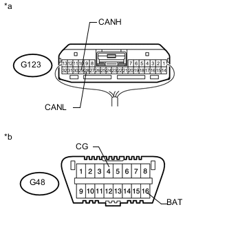
Text in Illustration *a Rear view of wire harness connector
(to Stabilizer Control ECU)
*b Front view of DLC3 Disconnect the G123 stabilizer control ECU connector.
-
Measure the resistance according to the value(s) in the table below.
Standard Resistance Tester Connection Switch Condition Specified Condition G123-29 (CANH) - G123- 28 (CANL) Engine switch off 54 to 69 Ω G123-29 (CANH) - G48-4 (CG) Engine switch off 200 Ω or higher G123-28 (CANL) - G48-4 (CG) Engine switch off 200 Ω or higher G123-29 (CANH) - G48- 16 (BAT) Engine switch off 6 kΩ or higher G123-28 (CANL) - G48- 16 (BAT) Engine switch off 6 kΩ or higher
OK
REPLACE STABILIZER CONTROL ECU Click here
NG
REPAIR OR REPLACE CAN BRANCH WIRE CONNECTED TO STABILIZER CONTROL ECU (CANH, CANL)
-
-
CONNECT CONNECTOR
-
Reconnect the G95 No. 2 junction connector.
NEXT
-
-
CHECK FOR SHORT IN CAN BUS WIRES (SEAT BELT CONTROL ECU)
-
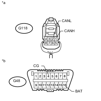
Text in Illustration *a Rear view of wire harness connector
(to Seat Belt Control ECU)
*b Front view of DLC3 Disconnect the G118 seat belt control ECU connector.
-
Measure the resistance according to the value(s) in the table below.
Standard Resistance Tester Connection Switch Condition Specified Condition G118-1 (CANH) - G118-2 (CANL) Engine switch off 54 to 69 Ω G118-1 (CANH) - G48-4 (CG) Engine switch off 200 Ω or higher G118-2 (CANL) - G48-4 (CG) Engine switch off 200 Ω or higher G118-1 (CANH) - G48-16 (BAT) Engine switch off 6 kΩ or higher G118-2 (CANL) - G48-16 (BAT) Engine switch off 6 kΩ or higher
OK
REPLACE SEAT BELT CONTROL ECU Click here
NG
REPAIR OR REPLACE CAN BRANCH WIRE CONNECTED TO SEAT BELT CONTROL ECU (CANH, CANL)
-
-
CONNECT CONNECTOR
-
Reconnect the G95 No. 2 junction connector.
NEXT
-
-
CHECK FOR SHORT IN CAN BUS WIRES (NO. 6 JUNCTION CONNECTOR - NO. 2 JUNCTION CONNECTOR)
-
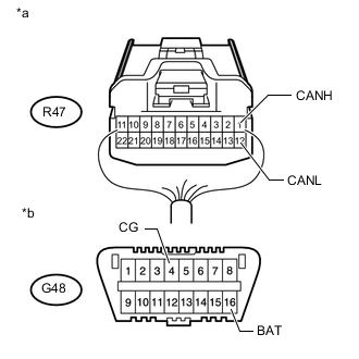
Text in Illustration *a Rear view of wire harness connector
(to No. 6 Junction Connector)
*b Front view of DLC3 Disconnect the R47 No. 6 junction connector.
-
Measure the resistance according to the value(s) in the table below.
Standard Resistance Tester Connection Switch Condition Specified Condition R47-1 (CANH) - R47-12 (CANL) Engine switch off 108 to 132 Ω R47-1 (CANH) - G48-4 (CG) Engine switch off 200 Ω or higher R47-12 (CANL) - G48-4 (CG) Engine switch off 200 Ω or higher R47-1 (CANH) - G48-16 (BAT) Engine switch off 6 kΩ or higher R47-12 (CANL) - G48-16 (BAT) Engine switch off 6 kΩ or higher
NG
REPAIR OR REPLACE CAN MAIN WIRE OR CONNECTOR (NO. 6 JUNCTION CONNECTOR - NO. 2 JUNCTION CONNECTOR)
OK
-
-
CHECK FOR SHORT IN CAN BUS WIRES (NO. 6 JUNCTION CONNECTOR SIDE)
-

Text in Illustration *A for 1KD-FTV *B for 1GR-FE, 1GD-FTV *a Component with harness connector
(Power Management Control ECU)
Measure the resistance according to the value(s) in the table below.
Standard Resistance for 1KD-FTV Tester Connection Switch Condition Specified Condition G51-26 (CA2H) - G51-25 (CA2L) Engine switch off 108 to 132 Ω G51-26 (CA2H) - G51-6 (GND) Engine switch off 200 Ω or higher G51-25 (CA2L) - G51-6 (GND) Engine switch off 200 Ω or higher G51-26 (CA2H) - G51-1 (AM22) Engine switch off 6 kΩ or higher G51-25 (CA2L) - G51-1 (AM22) Engine switch off 6 kΩ or higher for 1GR-FE, 1GD-FTV Tester Connection Switch Condition Specified Condition G51-12 (CA3P) - G51-11 (CA3N) Engine switch off 108 to 132 Ω G51-12 (CA3P) - G51-6 (GND) Engine switch off 200 Ω or higher G51-11 (CA3N) - G51-6 (GND) Engine switch off 200 Ω or higher G51-12 (CA3P) - G51-1 (AM22) Engine switch off 6 kΩ or higher G51-11 (CA3N) - G51-1 (AM22) Engine switch off 6 kΩ or higher
NG
CONNECT CONNECTOR Click here
OK
-
-
CHECK FOR SHORT IN CAN BUS WIRES (NO. 6 JUNCTION CONNECTOR - BLIND SPOT MONITOR SENSOR LH)
-
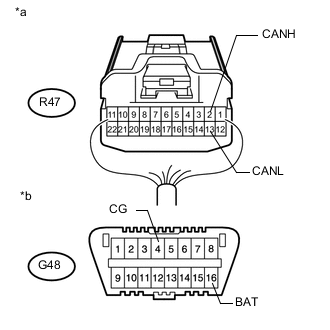
Text in Illustration *a Rear view of wire harness connector
(to No. 6 Junction Connector)
*b Front view of DLC3 Measure the resistance according to the value(s) in the table below.
Standard Resistance Tester Connection Switch Condition Specified Condition R47-2 (CANH) - R47-13 (CANL) Engine switch off 200 Ω or higher R47-2 (CANH) - G48-4 (CG) Engine switch off 200 Ω or higher R47-13 (CANL) - G48-4 (CG) Engine switch off 200 Ω or higher R47-2 (CANH) - G48-16 (BAT) Engine switch off 6 kΩ or higher R47-13 (CANL) - G48-16 (BAT) Engine switch off 6 kΩ or higher
OK
REPLACE NO. 6 JUNCTION CONNECTOR
NG
-
-
CONNECT CONNECTOR
-
Reconnect the R47 No. 6 junction connector.
NEXT
-
-
CHECK FOR SHORT IN CAN BUS WIRES (BLIND SPOT MONITOR SENSOR LH)
-
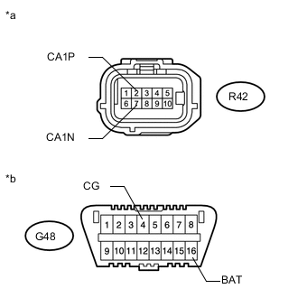
Text in Illustration *a Front view of wire harness connector
(to Blind Spot Monitor Sensor LH)
*b Front view of DLC3 Disconnect the R42 blind spot monitor sensor LH connector.
-
Measure the resistance according to the value(s) in the table below.
Standard Resistance Tester Connection Switch Condition Specified Condition R42-2 (CA1P) - R42-7 (CA1N) Engine switch off 54 to 69 Ω R42-2 (CA1P) - G48-4 (CG) Engine switch off 200 Ω or higher R42-7 (CA1N) - G48-4 (CG) Engine switch off 200 Ω or higher R42-2 (CA1P) - G48-16 (BAT) Engine switch off 6 kΩ or higher R42-7 (CA1N) - G48-16 (BAT) Engine switch off 6 kΩ or higher
OK
REPLACE BLIND SPOT MONITOR SENSOR LH Click here
NG
REPAIR OR REPLACE CAN BRANCH WIRE CONNECTED TO BLIND SPOT MONITOR SENSOR LH (CA1P, CA1N)
-
-
CONNECT CONNECTOR
-
Reconnect the R47 No. 6 junction connector.
NEXT
-
-
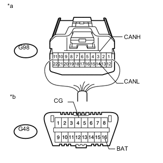
CHECK FOR SHORT IN CAN BUS WIRES (NO. 3 JUNCTION CONNECTOR - NO. 6 JUNCTION CONNECTOR)
-

Text in Illustration *a Rear view of wire harness connector
(to No. 3 Junction Connector)
*b Front view of DLC3 Disconnect the G98 No. 3 junction connector.
-
Measure the resistance according to the value(s) in the table below.
Standard Resistance Tester Connection Switch Condition Specified Condition G98-1 (CANH) - G98-12 (CANL) Engine switch off 108 to 132 Ω G98-1 (CANH) - G48-4 (CG) Engine switch off 200 Ω or higher G98-12 (CANL) - G48-4 (CG) Engine switch off 200 Ω or higher G98-1 (CANH) - G48-16 (BAT) Engine switch off 6 kΩ or higher G98-12 (CANL) - G48-16 (BAT) Engine switch off 6 kΩ or higher
NG
REPAIR OR REPLACE CAN MAIN WIRE OR CONNECTOR (NO. 3 JUNCTION CONNECTOR - NO. 6 JUNCTION CONNECTOR)
OK
-
-
CHECK FOR SHORT IN CAN BUS WIRES (NO. 3 JUNCTION CONNECTOR - SUSPENSION CONTROL ECU)
Note
For vehicles without an air suspension system, go to "Check for Short in CAN Bus Wires (No. 3 Junction Connector - Driving Support ECU Assembly)".
-
Text in Illustration *a Rear view of wire harness connector
(to No. 3 Junction Connector)
*b Front view of DLC3 Measure the resistance according to the value(s) in the table below.
Standard Resistance Tester Connection Switch Condition Specified Condition G98-3 (CANH) - G98-14 (CANL) Engine switch off 200 Ω or higher G98-3 (CANH) - G48-4 (CG) Engine switch off 200 Ω or higher G98-14 (CANL) - G48-4 (CG) Engine switch off 200 Ω or higher G98-3 (CANH) - G48-16 (BAT) Engine switch off 6 kΩ or higher G98-14 (CANL) - G48-16 (BAT) Engine switch off 6 kΩ or higher
NG
CONNECT CONNECTOR Click here
OK
-
-
CHECK FOR SHORT IN CAN BUS WIRES (NO. 3 JUNCTION CONNECTOR - DRIVING SUPPORT ECU ASSEMBLY)
Note
For vehicles without a pre-crash safety system, go to "Check for Short in CAN Bus Wires (No. 3 Junction Connector - Clearance Warning ECU Assembly)".
-
Text in Illustration *a Rear view of wire harness connector
(to No. 3 Junction Connector)
*b Front view of DLC3 Measure the resistance according to the value(s) in the table below.
Standard Resistance Tester Connection Switch Condition Specified Condition G98-4 (CANH) - G98-15 (CANL) Engine switch off 200 Ω or higher G98-4 (CANH) - G48-4 (CG) Engine switch off 200 Ω or higher G98-15 (CANL) - G48-4 (CG) Engine switch off 200 Ω or higher G98-4 (CANH) - G48-16 (BAT) Engine switch off 6 kΩ or higher G98-15 (CANL) - G48-16 (BAT) Engine switch off 6 kΩ or higher
NG
CONNECT CONNECTOR Click here
OK
-
-
CHECK FOR SHORT IN CAN BUS WIRES (NO. 3 JUNCTION CONNECTOR - CLEARANCE WARNING ECU ASSEMBLY)
Note
For vehicles without a TOYOTA parking assist-sensor system (for 8 sensor type), go to "Check for Short in CAN Bus Wires (No. 3 Junction Connector - Air Conditioning Amplifier Assembly)".
-

Text in Illustration *a Rear view of wire harness connector
(to No. 3 Junction Connector)
*b Front view of DLC3 Measure the resistance according to the value(s) in the table below.
Standard Resistance Tester Connection Switch Condition Specified Condition G98-5 (CANH) - G98-16 (CANL) Engine switch off 200 Ω or higher G98-5 (CANH) - G48-4 (CG) Engine switch off 200 Ω or higher G98-16 (CANL) - G48-4 (CG) Engine switch off 200 Ω or higher G98-5 (CANH) - G48-16 (BAT) Engine switch off 6 kΩ or higher G98-16 (CANL) - G48-16 (BAT) Engine switch off 6 kΩ or higher
NG
CONNECT CONNECTOR Click here
OK
-
-
CHECK FOR SHORT IN CAN BUS WIRES (NO. 3 JUNCTION CONNECTOR - AIR CONDITIONING AMPLIFIER ASSEMBLY)
Note
For vehicles with 1KD-FTV, go to "Check for Short in CAN Bus Wires (No. 3 Junction Connector - Power Management Control ECU)".
-
Text in Illustration *a Rear view of wire harness connector
(to No. 3 Junction Connector)
*b Front view of DLC3 Measure the resistance according to the value(s) in the table below.
Standard Resistance Tester Connection Switch Condition Specified Condition G98-6 (CANH) - G98-17 (CANL) Engine switch off 200 Ω or higher G98-6 (CANH) - G48-4 (CG) Engine switch off 200 Ω or higher G98-17 (CANL) - G48-4 (CG) Engine switch off 200 Ω or higher G98-6 (CANH) - G48-16 (BAT) Engine switch off 6 kΩ or higher G98-17 (CANL) - G48-16 (BAT) Engine switch off 6 kΩ or higher
NG
CONNECT CONNECTOR Click here
OK
-
-
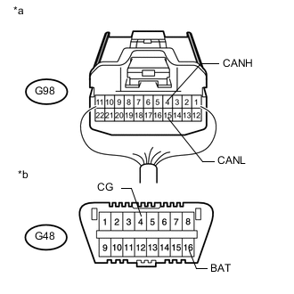
CHECK FOR SHORT IN CAN BUS WIRES (NO. 3 JUNCTION CONNECTOR - POWER MANAGEMENT CONTROL ECU)
-

Text in Illustration *a Rear view of wire harness connector
(to No. 3 Junction Connector)
*b Front view of DLC3 Measure the resistance according to the value(s) in the table below.
Standard Resistance Tester Connection Switch Condition Specified Condition G98-2 (CANH) - G98-13 (CANL) Engine switch off 108 to 132 Ω G98-2 (CANH) - G48-4 (CG) Engine switch off 200 Ω or higher G98-13 (CANL) - G48-4 (CG) Engine switch off 200 Ω or higher G98-2 (CANH) - G48-16 (BAT) Engine switch off 6 kΩ or higher G98-13 (CANL) - G48-16 (BAT) Engine switch off 6 kΩ or higher
OK
REPLACE NO. 3 JUNCTION CONNECTOR
NG
CONNECT CONNECTOR Click here
-
-
CONNECT CONNECTOR
-
Reconnect the G95 No. 2 junction connector.
NEXT
-
-
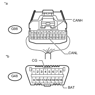
CHECK FOR SHORT IN CAN BUS WIRES (NO. 3 JUNCTION CONNECTOR - NO. 2 JUNCTION CONNECTOR)
-

Text in Illustration *a Rear view of wire harness connector
(to No. 3 Junction Connector)
*b Front view of DLC3 Disconnect the G98 No. 3 junction connector.
-
Measure the resistance according to the value(s) in the table below.
Standard Resistance Tester Connection Switch Condition Specified Condition G98-1 (CANH) - G98-12 (CANL) Engine switch off 108 to 132 Ω G98-1 (CANH) - G48-4 (CG) Engine switch off 200 Ω or higher G98-12 (CANL) - G48-4 (CG) Engine switch off 200 Ω or higher G98-1 (CANH) - G48-16 (BAT) Engine switch off 6 kΩ or higher G98-12 (CANL) - G48-16 (BAT) Engine switch off 6 kΩ or higher
NG
REPAIR OR REPLACE CAN MAIN WIRE OR CONNECTOR (NO. 3 JUNCTION CONNECTOR - NO. 2 JUNCTION CONNECTOR)
OK
-
-
CHECK FOR SHORT IN CAN BUS WIRES (NO. 3 JUNCTION CONNECTOR - SUSPENSION CONTROL ECU)
Note
For vehicles without an air suspension system, go to "Check for Short in CAN Bus Wires (No. 3 Junction Connector - Driving Support ECU Assembly)".
-
Text in Illustration *a Rear view of wire harness connector
(to No. 3 Junction Connector)
*b Front view of DLC3 Measure the resistance according to the value(s) in the table below.
Standard Resistance Tester Connection Switch Condition Specified Condition G98-3 (CANH) - G98-14 (CANL) Engine switch off 200 Ω or higher G98-3 (CANH) - G48-4 (CG) Engine switch off 200 Ω or higher G98-14 (CANL) - G48-4 (CG) Engine switch off 200 Ω or higher G98-3 (CANH) - G48-16 (BAT) Engine switch off 6 kΩ or higher G98-14 (CANL) - G48-16 (BAT) Engine switch off 6 kΩ or higher
NG
CONNECT CONNECTOR Click here
OK
-
-
CHECK FOR SHORT IN CAN BUS WIRES (NO. 3 JUNCTION CONNECTOR - DRIVING SUPPORT ECU ASSEMBLY)
Note
For vehicles without a pre-crash safety system, go to "Check for Short in CAN Bus Wires (No. 3 Junction Connector - Clearance Warning ECU Assembly)".
-

Text in Illustration *a Rear view of wire harness connector
(to No. 3 Junction Connector)
*b Front view of DLC3 Measure the resistance according to the value(s) in the table below.
Standard Resistance Tester Connection Switch Condition Specified Condition G98-4 (CANH) - G98-15 (CANL) Engine switch off 200 Ω or higher G98-4 (CANH) - G48-4 (CG) Engine switch off 200 Ω or higher G98-15 (CANL) - G48-4 (CG) Engine switch off 200 Ω or higher G98-4 (CANH) - G48-16 (BAT) Engine switch off 6 kΩ or higher G98-15 (CANL) - G48-16 (BAT) Engine switch off 6 kΩ or higher
NG
CONNECT CONNECTOR Click here
OK
-
-
CHECK FOR SHORT IN CAN BUS WIRES (NO. 3 JUNCTION CONNECTOR - CLEARANCE WARNING ECU ASSEMBLY)
Note
For vehicles without a TOYOTA parking assist-sensor system (for 8 sensor type), go to "Check for Short in CAN Bus Wires (No. 3 Junction Connector - Air Conditioning Amplifier Assembly)".
-
Text in Illustration *a Rear view of wire harness connector
(to No. 3 Junction Connector)
*b Front view of DLC3 Measure the resistance according to the value(s) in the table below.
Standard Resistance Tester Connection Switch Condition Specified Condition G98-5 (CANH) - G98-16 (CANL) Engine switch off 200 Ω or higher G98-5 (CANH) - G48-4 (CG) Engine switch off 200 Ω or higher G98-16 (CANL) - G48-4 (CG) Engine switch off 200 Ω or higher G98-5 (CANH) - G48-16 (BAT) Engine switch off 6 kΩ or higher G98-16 (CANL) - G48-16 (BAT) Engine switch off 6 kΩ or higher
NG
CONNECT CONNECTOR Click here
OK
-
-
CHECK FOR SHORT IN CAN BUS WIRES (NO. 3 JUNCTION CONNECTOR - AIR CONDITIONING AMPLIFIER ASSEMBLY)
Note
For vehicles with 1KD-FTV, go to "Check for Short in CAN Bus Wires (No. 3 Junction Connector - Power Management Control ECU)".
-

Text in Illustration *a Rear view of wire harness connector
(to No. 3 Junction Connector)
*b Front view of DLC3 Measure the resistance according to the value(s) in the table below.
Standard Resistance Tester Connection Switch Condition Specified Condition G98-6 (CANH) - G98-17 (CANL) Engine switch off 200 Ω or higher G98-6 (CANH) - G48-4 (CG) Engine switch off 200 Ω or higher G98-17 (CANL) - G48-4 (CG) Engine switch off 200 Ω or higher G98-6 (CANH) - G48-16 (BAT) Engine switch off 6 kΩ or higher G98-17 (CANL) - G48-16 (BAT) Engine switch off 6 kΩ or higher
NG
CONNECT CONNECTOR Click here
OK
-
-
CHECK FOR SHORT IN CAN BUS WIRES (NO. 3 JUNCTION CONNECTOR - POWER MANAGEMENT CONTROL ECU)
-

Text in Illustration *a Rear view of wire harness connector
(to No. 3 Junction Connector)
*b Front view of DLC3 Measure the resistance according to the value(s) in the table below.
Standard Resistance Tester Connection Switch Condition Specified Condition G98-2 (CANH) - G98-13 (CANL) Engine switch off 108 to 132 Ω G98-2 (CANH) - G48-4 (CG) Engine switch off 200 Ω or higher G98-13 (CANL) - G48-4 (CG) Engine switch off 200 Ω or higher G98-2 (CANH) - G48-16 (BAT) Engine switch off 6 kΩ or higher G98-13 (CANL) - G48-16 (BAT) Engine switch off 6 kΩ or higher
OK
REPLACE NO. 3 JUNCTION CONNECTOR
NG
CONNECT CONNECTOR Click here
-
-
CONNECT CONNECTOR
-
Reconnect the G98 No. 3 junction connector.
NEXT
-
-
CHECK FOR SHORT IN CAN BUS WIRES (SUSPENSION CONTROL ECU)
-
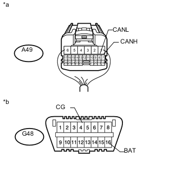
Text in Illustration *a Rear view of wire harness connector
(to Suspension Control ECU)
*b Front view of DLC3 Disconnect the A49 suspension control ECU connector.
-
Measure the resistance according to the value(s) in the table below.
Standard Resistance Tester Connection Switch Condition Specified Condition A49-7 (CANH) - A49-8 (CANL) Engine switch off 54 to 69 Ω A49-7 (CANH) - G48-4 (CG) Engine switch off 200 Ω or higher A49-8 (CANL) - G48-4 (CG) Engine switch off 200 Ω or higher A49-7 (CANH) - G48-16 (BAT) Engine switch off 6 kΩ or higher A49-8 (CANL) - G48-16 (BAT) Engine switch off 6 kΩ or higher
OK
REPLACE SUSPENSION CONTROL ECU Click here
NG
REPAIR OR REPLACE CAN BRANCH WIRE CONNECTED TO SUSPENSION CONTROL ECU (CANH, CANL)
-
-
CONNECT CONNECTOR
-
Reconnect the G98 No. 3 junction connector.
NEXT
-
-
CHECK FOR SHORT IN CAN BUS WIRES (DRIVING SUPPORT ECU ASSEMBLY)
-
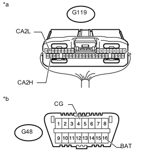
Text in Illustration *a Rear view of wire harness connector
(to Driving Support ECU Assembly)
*b Front view of DLC3 Disconnect the G119 driving support ECU assembly connector.
-
Measure the resistance according to the value(s) in the table below.
Standard Resistance Tester Connection Switch Condition Specified Condition G119-39 (CA2H) - G119- 17 (CA2L) Engine switch off 54 to 69 Ω G119-39 (CA2H) - G48-4 (CG) Engine switch off 200 Ω or higher G119-17 (CA2L) - G48-4 (CG) Engine switch off 200 Ω or higher G119-39 (CA2H) - G48- 16 (BAT) Engine switch off 6 kΩ or higher G119-17 (CA2L) - G48- 16 (BAT) Engine switch off 6 kΩ or higher
OK
REPLACE DRIVING SUPPORT ECU ASSEMBLY Click here
NG
REPAIR OR REPLACE CAN BRANCH WIRE CONNECTED TO DRIVING SUPPORT ECU ASSEMBLY (CA2H, CA2L)
-
-
CONNECT CONNECTOR
-
Reconnect the G98 No. 3 junction connector.
NEXT
-
-
CHECK FOR SHORT IN CAN BUS WIRES (CLEARANCE WARNING ECU ASSEMBLY)
-
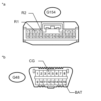
Text in Illustration *a Front view of wire harness connector
(to Clearance Warning ECU Assembly)
*b Front view of DLC3 Disconnect the G154 clearance warning ECU assembly connector.
-
Measure the resistance according to the value(s) in the table below.
Standard Resistance Tester Connection Switch Condition Specified Condition G154-3 (R1) - G154-5 (R2) Engine switch off 54 to 69 Ω G154-3 (R1) - G48-4 (CG) Engine switch off 200 Ω or higher G154-5 (R2) - G48-4 (CG) Engine switch off 200 Ω or higher G154-3 (R1) - G48-16 (BAT) Engine switch off 6 kΩ or higher G154-5 (R2) - G48-16 (BAT) Engine switch off 6 kΩ or higher
OK
REPLACE CLEARANCE WARNING ECU ASSEMBLY Click here
NG
REPAIR OR REPLACE CAN BRANCH WIRE CONNECTED TO CLEARANCE WARNING ECU ASSEMBLY (R1, R2)
-
-
CONNECT CONNECTOR
-
Reconnect the G98 No. 3 junction connector.
NEXT
-
-
CHECK FOR SHORT IN CAN BUS WIRES (AIR CONDITIONING AMPLIFIER ASSEMBLY)
-
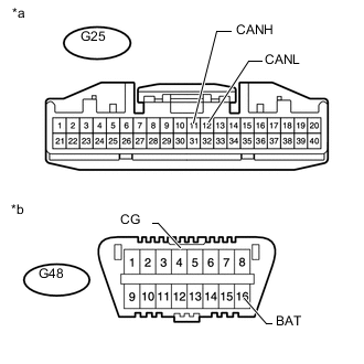
Text in Illustration *a Front view of wire harness connector
(to Air Conditioning Amplifier Assembly)
*b Front view of DLC3 Disconnect the G25 air conditioning amplifier assembly connector.
-
Measure the resistance according to the value(s) in the table below.
Standard Resistance Tester Connection Switch Condition Specified Condition G25-11 (CANH) - G25-12 (CANL) Engine switch off 54 to 69 Ω G25-11 (CANH) - G48-4 (CG) Engine switch off 200 Ω or higher G25-12 (CANL) - G48-4 (CG) Engine switch off 200 Ω or higher G25-11 (CANH) - G48-16 (BAT) Engine switch off 6 kΩ or higher G25-11 (CANH) - G48-16 (BAT) Engine switch off 6 kΩ or higher
OK
REPLACE AIR CONDITIONING AMPLIFIER ASSEMBLY Click here
NG
REPAIR OR REPLACE CAN BRANCH WIRE CONNECTED TO AIR CONDITIONING AMPLIFIER ASSEMBLY (CANH, CANL)
-
-
CONNECT CONNECTOR
-
Reconnect the G98 No. 3 junction connector.
NEXT
-
-
CHECK FOR SHORT IN CAN BUS WIRES (POWER MANAGEMENT CONTROL ECU)
-
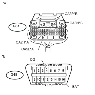
Text in Illustration *A for 1KD-FTV *B for 1GR-FE, 1GD-FTV *a Rear view of wire harness connector
(to Power Management Control ECU)
*b Front view of DLC3 Disconnect the G51 power management control ECU connector.
-
Measure the resistance according to the value(s) in the table below.
Standard Resistance for 1KD-FTV Tester Connection Switch Condition Specified Condition G51-26 (CA2H) - G51-25 (CA2L) Engine switch off 108 to 132 Ω G51-26 (CA2H) - G48-4 (CG) Engine switch off 200 Ω or higher G51-25 (CA2L) - G48-4 (CG) Engine switch off 200 Ω or higher G51-26 (CA2H) - G48-16 (BAT) Engine switch off 6 kΩ or higher G51-25 (CA2L) - G48-16 (BAT) Engine switch off 6 kΩ or higher for 1GR-FE, 1GD-FTV Tester Connection Switch Condition Specified Condition G51-12 (CA3P) - G51-11 (CA3N) Engine switch off 108 to 132 Ω G51-12 (CA3P) - G48-4 (CG) Engine switch off 200 Ω or higher G51-11 (CA3N) - G48-4 (CG) Engine switch off 200 Ω or higher G51-12 (CA3P) - G48-16 (BAT) Engine switch off 6 kΩ or higher G51-11 (CA3N) - G48-16 (BAT) Engine switch off 6 kΩ or higher Result Result Proceed to OK A NG (for 1KD-FTV) B NG (for 1GR-FE, 1GD-FTV) C
A
REPLACE POWER MANAGEMENT CONTROL ECU Click here
B
REPAIR OR REPLACE CAN MAIN WIRE CONNECTED TO POWER MANAGEMENT CONTROL ECU (CA2H, CA2L)
C
REPAIR OR REPLACE CAN MAIN WIRE CONNECTED TO POWER MANAGEMENT CONTROL ECU (CA3P, CA3H)
-
-
CHECK HARNESS AND CONNECTOR (POWER MANAGEMENT CONTROL ECU - BATTERY AND BODY GROUND)
-
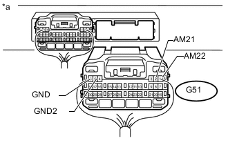
Text in Illustration *a Rear view of wire harness connector
(to Power Management Control ECU)
Connect the cable to the negative (-) battery terminal.
Note
When disconnecting the cable, some systems need to be initialized after the cable is reconnected Click here
-
Disconnect the G51 power management control ECU connector.
-
Measure the resistance according to the value(s) in the table below.
Standard Resistance Tester Connection Condition Specified Condition G51-5 (GND2) - Body ground Always Below 1 Ω G51-6 (GND) - Body ground Always Below 1 Ω -
Measure the voltage according to the value(s) in the table below.
Standard Voltage Tester Connection Condition Specified Condition G51-1 (AM22) - Body ground Always 11 to 14 V G51-2 (AM21) - Body ground Always 11 to 14 V
OK
REPLACE POWER MANAGEMENT CONTROL ECU Click here
NG
REPAIR OR REPLACE HARNESS OR CONNECTOR
-