TOYOTA PARKING ASSIST-SENSOR SYSTEM(w/ Multi-display) Main Switch Circuit
DESCRIPTION
for 4 Sensor Type:
When the back sonar or clearance sonar switch assembly is turned on, the on signal is input into the ECU.
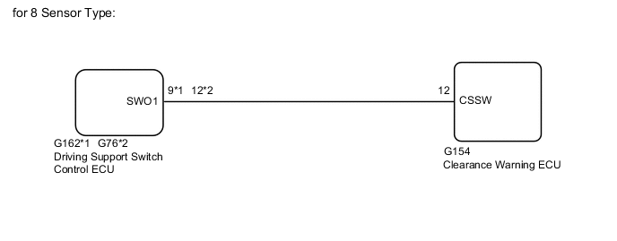
for 8 Sensor Type
When the driving support switch control ECU receives the clearance sonar on/off switch signal, the ECU sends it to the clearance warning ECU.
WIRING DIAGRAM
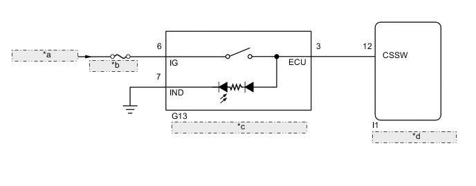
| *a | from IG1 NO.1 Relay |
| *b | ECU-IG NO. 2 |
| *c | Back Sonar or Clearance Sonar Switch Assembly |
| *d | Clearance Warning ECU |
CAUTION / NOTICE / HINT
Note
Inspect the fuses for circuits related to this system before performing the following inspection procedure.
PROCEDURE
-
READ VALUE USING GTS
-
Connect the GTS to the DLC3.
-
Turn the engine switch on (IG).
-
Turn the GTS on.
-
Enter the following menus: Body / Clearance Sonar / Data List.
-
According to the display on the GTS, read the Data List.
Clearance Sonar Tester Display Measurement Item/Range Normal Condition Diagnostic Note Main Switch TOYOTA parking assist-sensor system (multi-function switch)/OFF or ON OFF: TOYOTA parking assist-sensor system off
ON: TOYOTA parking assist-sensor system on
- OK The display changes as shown above when the TOYOTA parking assist-sensor system is operated. Result Result Proceed to OK A NG (for 4 Sensor Type) B NG (for 8 Sensor Type) C
A 
PROCEED TO NEXT SUSPECTED AREA SHOWN IN PROBLEM SYMPTOMS TABLE Click here
C 
CHECK HARNESS AND CONNECTOR (DRIVING SUPPORT SWITCH CONTROL ECU - CLEARANCE WARNING ECU) Click here
B 
-
-
INSPECT BACK SONAR OR CLEARANCE SONAR SWITCH ASSEMBLY
-
Remove the back sonar or clearance sonar switch assembly Click here.
-
Inspect the back sonar or clearance sonar switch assembly Click here.
NG
REPLACE BACK SONAR OR CLEARANCE SONAR SWITCH ASSEMBLY Click here
OK
-
-
CHECK HARNESS AND CONNECTOR (BACK SONAR OR CLEARANCE SONAR SWITCH ASSEMBLY - CLEARANCE WARNING ECU, BATTERY AND BODY GROUND)
-
Disconnect the G13 back sonar or clearance sonar switch assembly connector.
-
Disconnect the I1 clearance warning ECU connector.
-
Measure the resistance according to the value(s) in the table below.
Standard Resistance Tester Connection Switch Condition Specified Condition G13-6 (IG) - Body ground Engine switch on (IG) 11 to 14 V -
Measure the resistance according to the value(s) in the table below.
Standard Resistance Tester Connection Condition Specified Condition G13-3 (ECU) - I1-12 (CSSW) Always Below 1 Ω G13-7 (IND) - Body ground Always Below 1 Ω G13-3 (ECU) - Body ground Always 10 kΩ or higher Result Result Proceed to OK (for LHD) A OK (for RHD) B NG C
A
REPLACE CLEARANCE WARNING ECU Click here
B
REPLACE CLEARANCE WARNING ECU Click here
C
REPAIR OR REPLACE HARNESS OR CONNECTOR
-
-
CHECK HARNESS AND CONNECTOR (DRIVING SUPPORT SWITCH CONTROL ECU - CLEARANCE WARNING ECU)
-
Disconnect the G162*1 or G76*2 driving support switch control ECU connector.
-
*1: for Automatic Transmission
-
*2: for Manual Transmission
-
-
Disconnect the G154 clearance warning ECU connector.
-
Measure the resistance according to the value(s) in the table below.
Standard Resistance for Automatic Transmission Tester Connection Condition Specified Condition G162-9 (SWO1) - G154-12 (CSSW) Always Below 1 Ω G162-9 (SWO1) - Body ground Always 10 kΩ or higher for Manual Transmission Tester Connection Condition Specified Condition G76-12 (SWO1) - G154-12 (CSSW) Always Below 1 Ω G76-12 (SWO1) - Body ground Always 10 kΩ or higher
NG
REPAIR OR REPLACE HARNESS OR CONNECTOR
OK
-
-
CHECK DRIVING SUPPORT SWITCH CONTROL ECU
-
Replace the driving support switch control ECU with a new or normally functioning one Click here.
-
Check the TOYOTA parking assist-sensor system operates normally.
OK TOYOTA parking assist-sensor system operates normally. Result Result Proceed to OK A NG (for LHD) B NG (for RHD) C
A
END (DRIVING SUPPORT SWITCH CONTROL ECU IS DEFECTIVE)
B
REPLACE CLEARANCE WARNING ECU Click here
C
REPLACE CLEARANCE WARNING ECU Click here
-