NAVIGATION SYSTEM(for Radio and Display Type), Diagnostic DTC:B15C0, B15C1
| DTC Code | DTC Name |
|---|---|
| B15C0 | Short in GPS Antenna |
| B15C1 | Open in GPS Antenna |
DESCRIPTION
These DTCs are stored when a malfunction occurs in the navigation antenna assembly.
| DTC Code | DTC Detection Condition | Trouble Area |
|---|---|---|
| B15C0 | Navigation antenna error |
|
| B15C1 | Error of the power source to the navigation antenna |
-
*1: w/o Windshield Deicer System
-
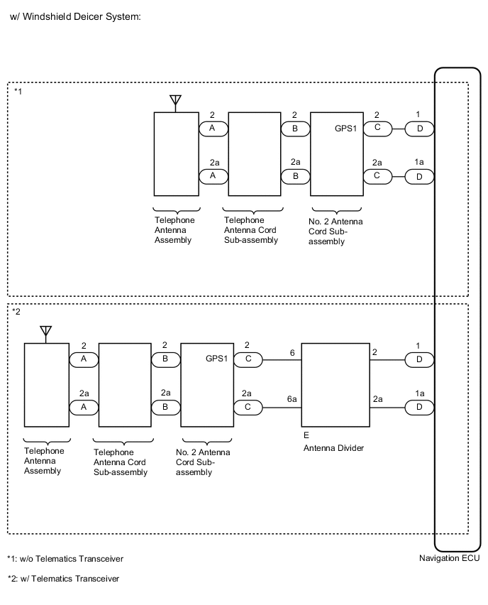
*2: w/ Windshield Deicer System
-
*3: w/ Windshield Deicer System and w/ Telematics Transceiver
WIRING DIAGRAM
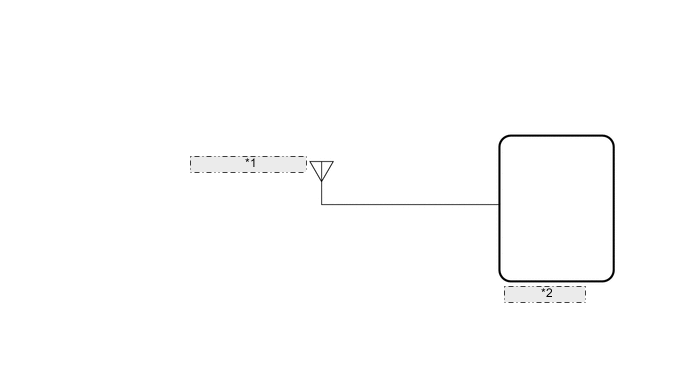
| *1 | Navigation Antenna Assembly |
| *2 | Navigation ECU |
PROCEDURE
-
CLEAR DTC
-
Clear the DTCs.
Result Proceed to NEXT
NEXT 
-
-
CHECK DTC
-
Recheck for DTCs and check if the same DTC is output again.
OK No DTCs are output. Result Proceed to OK NG
OK 
USE SIMULATION METHOD TO CHECK Click here
NG
-
-
CHECK VEHICLE CONDITION
-
Check the vehicle condition.
Result Result Proceed to w/o Windshield Deicer System A w/ Windshield Deicer System B
B 
CHECK VEHICLE CONDITION Click here
A
-
-
CHECK CONNECTION OF NAVIGATION ANTENNA ASSEMBLY
-
Check if the navigation antenna assembly is securely connected to the navigation ECU.
OK Navigation antenna assembly is securely connected. Result Proceed to OK NG
NG
SECURELY CONNECT NAVIGATION ANTENNA ASSEMBLY
OK
-
-
INSPECT NAVIGATION ECU
-
Remove the navigation antenna assembly.
-
Inspect the navigation antenna assembly.
Result Proceed to OK NG
OK
REPLACE NAVIGATION ECU Click here
NG
REPLACE NAVIGATION ANTENNA ASSEMBLY Click here
-
-
CHECK VEHICLE CONDITION
-
Check the vehicle condition.
Result Result Proceed to w/o Telematics Transceiver A w/ Telematics Transceiver B
B
INSPECT TELEPHONE ANTENNA CORD SUB-ASSEMBLY Click here
A
-
-
INSPECT TELEPHONE ANTENNA CORD SUB-ASSEMBLY
-
Disconnect the antenna connector from the telephone antenna assembly.
-
Disconnect the antenna connector from the No. 2 antenna cord sub-assembly.
-

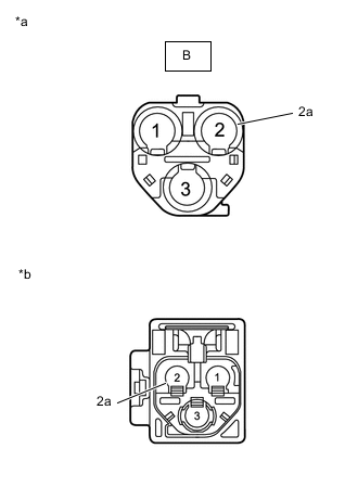
*a Front view of wire harness connector
(to Telephone Antenna Assembly)
*a Front view of wire harness connector
(to No. 2 Antenna Cord Sub-assembly)
Measure the resistance according to the value(s) in the table below.
Standard Resistance Tester Connection Condition Specified Condition A-2 - B-2 Always Below 1 Ω A-2a - B-2a Always Below 1 Ω A-2 or B-2 - Body ground Always 10 kΩ or higher A-2a or B-2a - Body ground Always 10 kΩ or higher Result Proceed to OK NG
NG
REPLACE TELEPHONE ANTENNA CORD SUB-ASSEMBLY Click here
OK
-
-
INSPECT NO. 2 ANTENNA CORD SUB-ASSEMBLY
-
Disconnect the antenna connector from the telephone antenna cord sub-assembly.
-
Disconnect the antenna connector from the wire harness.
-
*a Front view of wire harness connector
(to Telephone Antenna Cord Sub-assembly)
*a Front view of wire harness connector
(to Wire Harness)
Measure the resistance according to the value(s) in the table below.
Standard Resistance Tester Connection Condition Specified Condition B-2 - 2 Always Below 1 Ω B-2a - 2a Always Below 1 Ω B-2 - Body ground Always 10 kΩ or higher B-2a - Body ground Always 10 kΩ or higher Result Proceed to OK NG
NG
REPLACE NO. 2 ANTENNA CORD SUB-ASSEMBLY Click here
OK
-
-
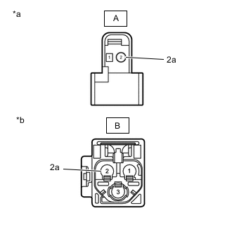
CHECK HARNESS AND CONNECTOR (NO. 2 ANTENNA CORD SUB-ASSEMBLY - TELEMATICS TRANSCEIVER [DATA COMMUNICATION MODULE (DCM)])
-
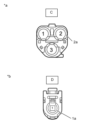
*a Front view of wire harness connector
(to No. 2 Antenna Cord Sub-assembly)
*b Front view of wire harness connector
(to navigation ECU)
Disconnect the No. 2 antenna cord sub-assembly connector.
-
Disconnect the navigation ECU connector.
-
Measure the resistance according to the value(s) in the table below.
Standard Resistance Tester Connection Condition Specified Condition C-2 - D-1 Always Below 1 Ω C-2a - D-1a Always Below 1 Ω C-2 - Body ground Always 10 kΩ or higher C-2a - Body ground Always 10 kΩ or higher Result Proceed to OK NG
NG
REPAIR OR REPLACE HARNESS OR CONNECTOR
OK
-
-
CHECK TELEPHONE ANTENNA ASSEMBLY
-
Replace the telephone antenna assembly with a new or known good one.
-
Clear the DTCs.
-
Recheck for DTCs and check that no DTCs are output.
OK No DTCs are output. Result Proceed to OK NG
OK
END (TELEPHONE ANTENNA ASSEMBLY IS DEFECTIVE)
NG
REPLACE NAVIGATION ECU Click here
-
-
INSPECT TELEPHONE ANTENNA CORD SUB-ASSEMBLY
-
Disconnect the antenna connector from the telephone antenna assembly.
-
Disconnect the antenna connector from the No. 2 antenna cord sub-assembly.
-
*a Front view of wire harness connector
(to Telephone Antenna Assembly)
*b Front view of wire harness connector
(to No. 2 Antenna Cord Sub-assembly)
Measure the resistance according to the value(s) in the table below.
Standard Resistance Tester Connection Condition Specified Condition A-2 - B-2 Always Below 1 Ω A-2a - B-2a Always Below 1 Ω A-2 or B-2 - Body ground Always 10 kΩ or higher A-2a or B-2a - Body ground Always 10 kΩ or higher Result Proceed to OK NG
NG
REPLACE TELEPHONE ANTENNA CORD SUB-ASSEMBLY Click here
OK
-
-
INSPECT NO. 2 ANTENNA CORD SUB-ASSEMBLY
-
Disconnect the antenna connector from the telephone antenna cord sub-assembly.
-
Disconnect the antenna connector from the wire harness.
-

*a Front view of wire harness connector
(to Telephone Antenna Cord Sub-assembly)
*b Front view of wire harness connector
(to Wire Harness)
Measure the resistance according to the value(s) in the table below.
Standard Resistance Tester Connection Condition Specified Condition B-2 - 2 Always Below 1 Ω B-2a - 2a Always Below 1 Ω B-2 - Body ground Always 10 kΩ or higher B-2a - Body ground Always 10 kΩ or higher Result Proceed to OK NG
NG
REPLACE NO. 2 ANTENNA CORD SUB-ASSEMBLY Click here
OK
-
-
CHECK HARNESS AND CONNECTOR (NO. 2 ANTENNA CORD SUB-ASSEMBLY - ANTENNA DIVIDER)
-
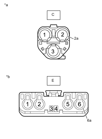
*a Front view of wire harness connector
(to No. 2 Antenna Cord Sub-assembly)
*b Front view of wire harness connector
(to Antenna Divider)
Disconnect the No. 2 antenna cord sub-assembly connector.
-
Disconnect the antenna divider connector.
-
Measure the resistance according to the value(s) in the table below.
Standard Resistance Tester Connection Condition Specified Condition C-2 - E-6 Always Below 1 Ω C-2a - E-6a Always Below 1 Ω C-2 - Body ground Always 10 kΩ or higher C-2a - Body ground Always 10 kΩ or higher Result Proceed to OK NG
NG
REPAIR OR REPLACE HARNESS OR CONNECTOR
OK
-
-
INSPECT ANTENNA DIVIDER
-
Remove the antenna divider.
-
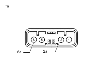
*a Component without harness connected
(Antenna Divider)
Measure the resistance according to the value(s) in the table below.
Standard Resistance Tester Connection Condition Specified Condition 6 - 2 Always 10 kΩ or higher 2 - 2a Always 243 to 267 Ω 6 - 6a Always 10 kΩ or higher Result Proceed to OK NG
NG
REPLACE ANTENNA DIVIDER Click here
OK
-
-
CHECK HARNESS AND CONNECTOR (ANTENNA DIVIDER - MULTI-MEDIA MODULE RECEIVER ASSEMBLY)
-
Disconnect the antenna divider connector.
-
Disconnect the multi-media module receiver assembly connector.
-
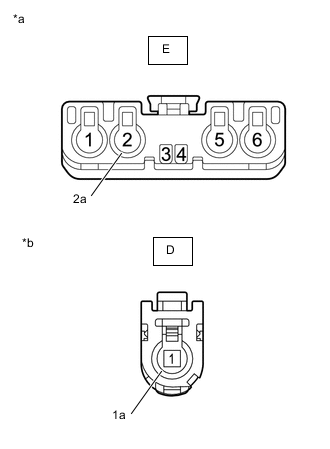
*a Front view of wire harness connector
(to Antenna Divider)
*a Front view of wire harness connector
(to Multi-media Module Receiver Assembly)
Measure the resistance according to the value(s) in the table below.
Standard Resistance Tester Connection Condition Specified Condition E-2 - D-1 Always Below 1 Ω E-2a - D-1a Always Below 1 Ω E-2 or D-1 - Body ground Always 10 kΩ or higher E-2a or D-1a - Body ground Always 10 kΩ or higher Result Proceed to OK NG
NG
REPAIR OR REPLACE HARNESS OR CONNECTOR
OK
-
-
CHECK TELEPHONE ANTENNA ASSEMBLY
-
Replace the telephone antenna assembly with a new or known good one.
-
Clear the DTCs.
Click here
-
Recheck for DTCs and check that no DTCs are output.
OK No DTCs are output. Result Proceed to OK NG
OK
END (TELEPHONE ANTENNA ASSEMBLY IS DEFECTIVE)
NG
-
-
CHECK ANTENNA DIVIDER
-
Replace the antenna divider with a new or known good one.
-
Clear the DTCs.
-
Check for DTCs.
OK No DTCs are output. Result Proceed to OK NG
OK
END (ANTENNA DIVIDER IS DEFECTIVE)
NG
REPLACE NAVIGATION ECU Click here
-