AMPLIFIER ANTENNA INSTALLATION
PROCEDURE
-
INSTALL HOLDER ANTENNA ASSEMBLY (for 5 Door)
-
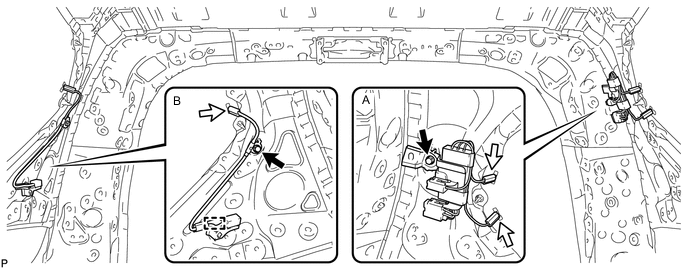
for Diversity:
-
Install the holder antenna with the bolt as shown in the part of the illustration labeled A.
- Torque:
- 7.0 N*m { 71 kgf*cm, 62 in.*lbf }
-
Attach the clamp and install the holder antenna with the bolt as shown in the part of the illustration labeled B.
- Torque:
- 7.5 N*m { 76 kgf*cm, 66 in.*lbf }
-
Connect the 3 connectors.
-
-
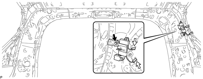
for Non Diversity:
-
Install the holder antenna with the bolt.
- Torque:
- 7.0 N*m { 71 kgf*cm, 62 in.*lbf }
-
Connect the 2 connectors.
-
-
-
INSTALL HOLDER ANTENNA ASSEMBLY (for 3 Door)
-
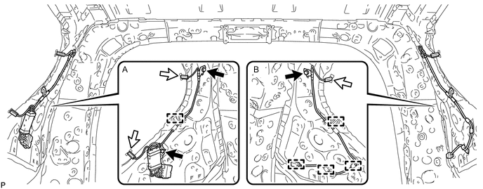
for Diversity:
-
Attach the clamp and install the holder antenna with the 2 bolts as shown in the part of the illustration labeled A.
- Torque:
- 8.0 N*m { 82 kgf*cm, 71 in.*lbf }
-
Attach the 4 clamps and install the holder antenna with the bolt as shown in the part of the illustration labeled B.
- Torque:
- 7.5 N*m { 76 kgf*cm, 66 in.*lbf }
-
Connect the 3 connectors.
-
-
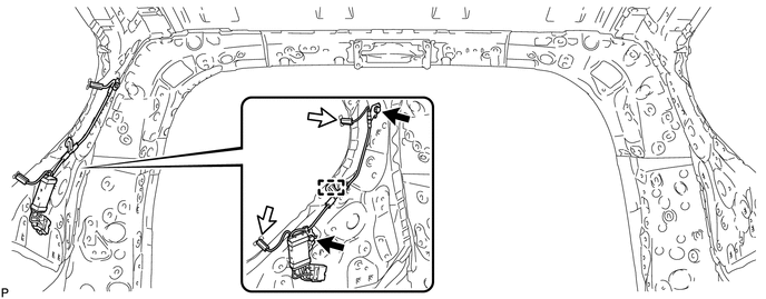
for Non Diversity:
-
Attach the clamp and install the holder antenna with the 2 bolts.
- Torque:
- 8.0 N*m { 82 kgf*cm, 71 in.*lbf }
-
Connect the 2 connectors.
-
-
-
INSTALL ROOF HEADLINING ASSEMBLY
-
for 5 Door:
-
for 3 Door:
-
-
CONNECT CABLE TO NEGATIVE BATTERY TERMINAL
Note
When disconnecting the cable, some systems need to be initialized after the cable is reconnected Click here.