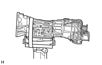
AUTOMATIC TRANSMISSION ASSEMBLY(for 1GD-FTV) REMOVAL

CAUTION / NOTICE / HINT
CAUTION:
The automatic transmission assembly is very heavy. Be sure to follow the procedure described in the repair manual, or the engine lifter may suddenly drop.
PROCEDURE
-
PRECAUTION
Note
After turning the engine switch off, waiting time may be required before disconnecting the cable from the battery terminal. Therefore, make sure to read the disconnecting the cable from the battery terminal notice before proceeding with work.
-
DISCONNECT CABLE FROM NEGATIVE BATTERY TERMINAL
Note
When disconnecting the cable, some systems need to be initialized after the cable is reconnected.
-
REMOVE NO. 1 ENGINE UNDER COVER SUB-ASSEMBLY
-
REMOVE REAR ENGINE UNDER COVER ASSEMBLY
-
DRAIN AUTOMATIC TRANSMISSION FLUID
-
DRAIN TRANSFER OIL
-
REMOVE PROPELLER SHAFT ASSEMBLY
-
REMOVE FRONT PROPELLER SHAFT ASSEMBLY
-
REMOVE FRONT EXHAUST PIPE ASSEMBLY
-
DISCONNECT STARTER ASSEMBLY
-
for 2.0 kW Type:
-
Remove the 2 bolts and nut and disconnect the starter assembly.
Tech Tips
Tie the starter assembly with a string.
-
-
for 2.7 kW Type:
-
Remove the bolt and 2 nuts and disconnect the starter assembly.
Tech Tips
Tie the starter assembly with a string.
-
-
-
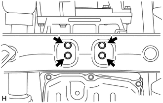
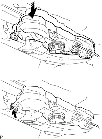
REMOVE OIL PAN INSULATOR
-
Disconnect the 2 wire harness clamps.
-
Remove the 2 bolts and oil pan insulator.
-
-
REMOVE DRIVE PLATE AND TORQUE CONVERTER ASSEMBLY SETTING BOLT
-
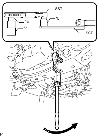
*a Socket Adaptor (Square drive 12.7 to 9.5 mm)
(Tool No. 09022-3C110)
*b Socket Adaptor (Square drive 9.5 mm to 12.7 mm)
(Tool No. 09022-3C100)
*c 17 mm Socket Wrench
(Tool No. 09011-2C500)

Turn Using SST, turn the crankshaft to gain access to the locations of the 6 drive plate and torque converter assembly setting bolts and remove each bolt while holding the crankshaft pulley bolt with a wrench.
Tech Tips
There will be one black colored bolt.
- SST
- 09961-01270
- 09970-10010 ( 09970-00010 )
-
-
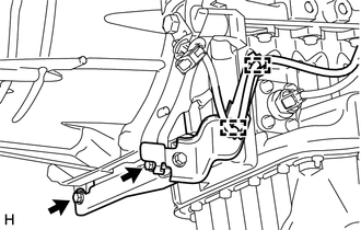
DISCONNECT TRANSMISSION CONTROL CABLE ASSEMBLY
-
Remove the clip and nut and disconnect the transmission control cable assembly from the transmission control shaft lever LH and transmission control cable bracket.
-
-
REMOVE TRANSMISSION INSULATOR RH
-
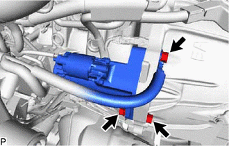
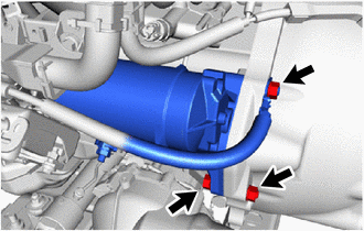
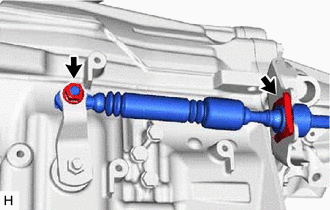
DISCONNECT OIL COOLER TUBE
-
Disconnect the 2 oil cooler tubes from the automatic transmission assembly.
Tech Tips
Use a container to catch any ATF.
-
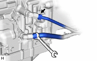
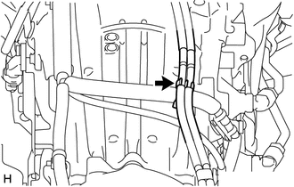
Remove the bolt and flexible hose clamp.
Text in Illustration *1 Flexible Hose Clamp - - -
Remove the 2 bolts and disconnect the 2 oil cooler tubes from the automatic transmission assembly.
-
-
REMOVE FRONT SUSPENSION MEMBER BRACKET LH AND RH
-
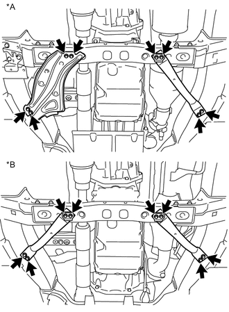
Text in Illustration *A w/ Urea SCR System *A w/o Urea SCR System Remove the 8 bolts, front suspension member bracket LH and RH from the No. 3 frame crossmember sub-assembly and vehicle body.
-
-
SUPPORT AUTOMATIC TRANSMISSION ASSEMBLY
-
Support the automatic transmission assembly with a transmission jack.
Note
-
In order to protect the automatic transmission oil pan sub-assembly, place attachments on the transmission jack.
-
Make sure that the attachments and the automatic transmission oil pan sub-assembly are centered on the transmission jack.
-
To prevent the automatic transmission oil pan sub-assembly from deforming, do not place any attachments under the automatic transmission oil pan sub-assembly of the automatic transmission assembly.
-
Secure the automatic transmission assembly to the transmission jack using a belt, etc. to prevent it from falling.
-
-
-
DISCONNECT UREA TANK SUB-ASSEMBLY
-
REMOVE NO. 3 FRAME CROSSMEMBER SUB-ASSEMBLY
-
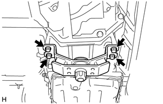
Remove the 4 bolts and disconnect the No. 3 frame crossmember sub-assembly from the rear No. 1 engine mounting insulator.
-
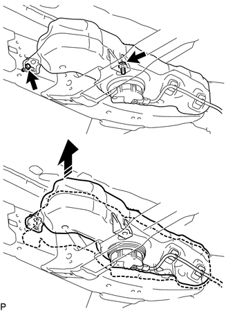
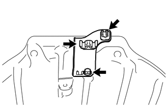
w/ Urea SCR System:
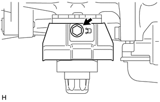
Remove the 2 bolts as shown in the illustration, raise the urea tank sub-assembly and hold it in position.
Tech Tips
Only raise the urea tank enough to remove the fixing bolts on the No. 3 frame crossmember sub-assembly. Do not raise it any higher.
-
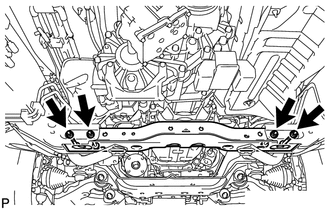
Remove the 4 bolts, 4 nuts and No. 3 frame crossmember sub-assembly from the vehicle body.
-
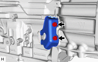
w/ Urea SCR System:
Temporarily install the urea tank sub-assembly with the bolt as shown in the illustration.
-
-
REMOVE REAR NO. 1 ENGINE MOUNTING INSULATOR
-
w/ Heat Insulator:
Remove the bolt and engine mounting heat insulator from the rear No. 1 engine mounting insulator.
-
Remove the 4 bolts and rear No. 1 engine mounting insulator from the automatic transmission assembly.
-
-
DISCONNECT WIRE HARNESS
-
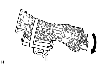
Tilt down the automatic transmission assembly.
Note
Make sure that the cooling fan and fan shroud do not contact the engine assembly when tilting the automatic transmission assembly.
-
Disconnect the breather hose from the wire harness.
-
Disconnect the park/neutral position switch connector, transmission wire connector, 2 speed sensor connectors and transfer connector.
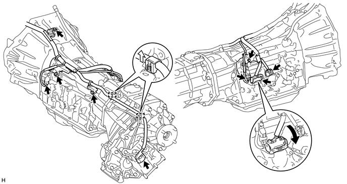
Tech Tips
Detach the claw, press down the lever, and then disconnect the transmission wire connector.
-
Detach the 2 wire harness clamps.
-
Remove the 4 bolts and disconnect the wire harness from the automatic transmission assembly.
-
-
REMOVE AUTOMATIC TRANSMISSION ASSEMBLY
-
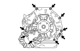
Remove the 9 bolts and automatic transmission assembly from the engine assembly.
Note
To prevent damage to the 2 knock pins, do not pry between the automatic transmission assembly and engine assembly.
-
-
REMOVE TRANSMISSION BREATHER BRACKET
Tech Tips
It is not necessary to remove the transmission breather bracket unless it is being replaced.
-
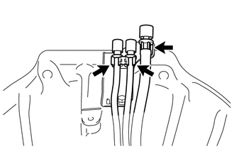
Disconnect the 3 breather hoses from the transmission breather bracket.
-
Remove the bolt and transmission breather bracket from the automatic transmission assembly.
-
Remove the 2 clamps from the transmission breather bracket.
-
-
REMOVE TRANSFER ASSEMBLY
-
REMOVE TRANSMISSION CONTROL CABLE BRACKET
Tech Tips
It is not necessary to remove the transmission control cable bracket unless it is being replaced.
-
Remove the 2 bolts and transmission control cable bracket from the automatic transmission assembly.
-
-
REMOVE TRANSMISSION OIL PAN HEAT INSULATOR
Tech Tips
It is not necessary to remove the transmission oil pan heat insulator unless it is being replaced.
-
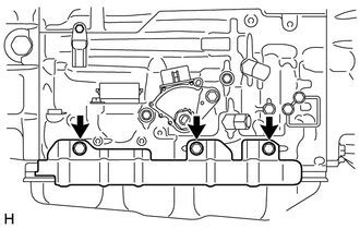
Remove the 3 bolts and transmission oil pan heat insulator from the automatic transmission assembly.
-
-
REMOVE TORQUE CONVERTER ASSEMBLY
-
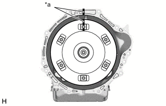
Text in Illustration *a Matchmark Put matchmarks on the automatic transmission assembly and the torque converter assembly.
-
Remove the torque converter assembly from the automatic transmission assembly.
Note
Remove the torque converter assembly from the input shaft horizontally.
-
-
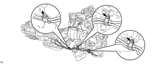
REMOVE WIRE HARNESS CLAMP BRACKET
Tech Tips
It is not necessary to remove the wire harness clamp brackets unless they are being replaced.
-
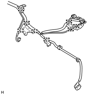
Detach the 8 wire harness clamps and 4 wire harness clamp brackets from the wire harness.
-
-
INSPECT TORQUE CONVERTER ASSEMBLY
-
INSPECT PUMP IMPELLER DRIVE PLATE