DRIVING SUPPORT ECU INSTALLATION
CAUTION / NOTICE / HINT
Note
-
Do not twist the connectors of the driving support ECU when connecting them.
-
Do not apply more force than necessary to the connectors. If more than 98 N (10 kgf, 22 lbf) of force is applied to a connector, the connector or connector holder may be damaged.
Tech Tips
-
A bolt without a torque specification is shown in the standard bolt chart Click here.
-
Use the same procedure for RHD and LHD vehicles.
-
The procedure listed below is for LHD vehicles.
PROCEDURE
-
INSTALL DRIVING SUPPORT ECU ASSEMBLY
-
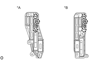
*A for LHD *B for RHD Attach the 3 claws to install the driving support ECU assembly.
-
-
INSTALL ECU INTEGRATION BOX LH (for RHD)
-
INSTALL ECU INTEGRATION BOX RH (for LHD)
-
INSTALL NO. 2 AIR DUCT SUB-ASSEMBLY
-
INSTALL GLOVE COMPARTMENT DOOR ASSEMBLY
-
INSTALL INSTRUMENT PANEL ORNAMENT
-
INSTALL INSTRUMENT SIDE PANEL RH
-
INSTALL FRONT DOOR OPENING TRIM WEATHERSTRIP RH
-
INSTALL NO. 2 INSTRUMENT PANEL UNDER COVER SUB-ASSEMBLY
-
INSTALL COWL SIDE TRIM BOARD RH
-
INSTALL DOOR SCUFF PLATE ASSEMBLY RH
-
CONNECT CABLE TO NEGATIVE BATTERY TERMINAL
Note
When disconnecting the cable, some systems need to be initialized after the cable is reconnected.