METER / GAUGE SYSTEM Speed Signal Circuit
DESCRIPTION
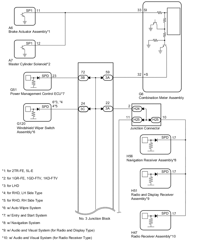
The vehicle speed signal consists of pulses sent to the combination meter assembly from the master cylinder solenoid*1 or brake actuator assembly (skid control ECU)*2.
-
*1: for 1GR-FE, 1KD-FTV, 1GD-FTV
-
*2: for 2TR-FE, 5L-E
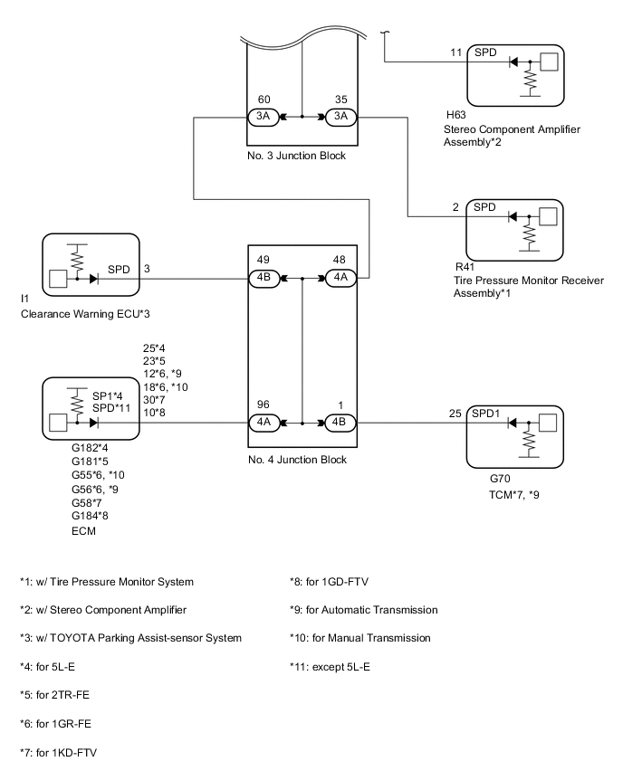
WIRING DIAGRAM
PROCEDURE
-
CHECK COMBINATION METER ASSEMBLY (INPUT VOLTAGE)
-
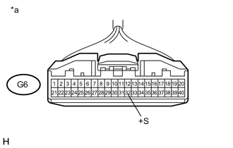
Text in Illustration *a Front view of wire harness connector
(to Combination Meter Assembly)
Disconnect the combination meter assembly connector.
-
Measure the voltage according to the value(s) in the table below.
Standard Voltage Tester Connection Switch Condition Specified Condition G6-32 (+S) - Body ground Ignition switch ON 4.5 to 14 V
NG 
CHECK HARNESS AND CONNECTOR (COMBINATION METER ASSEMBLY - NO. 3 JUNCTION BLOCK) Click here
OK 
-
-
CHECK COMBINATION METER ASSEMBLY (OUTPUT VOLTAGE)
-
for 1GR-FE, 1KD-FTV, 1GD-FTV:
-
Disconnect the master cylinder solenoid (skid control ECU) connector.
-
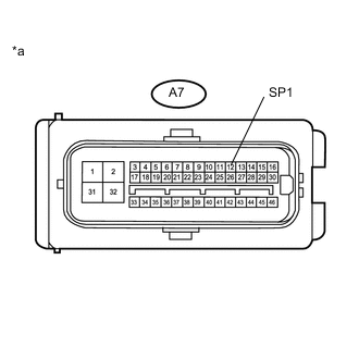
Text in Illustration *a Front view of wire harness connector
(to Master Cylinder Solenoid [Skid Control ECU])
Measure the voltage according to the value(s) in the table below.
Standard Voltage Tester Connection Switch Condition Specified Condition A7-12 (SP1) - Body ground Ignition switch ON 11 to 14 V
-
-
for 2TR-FE, 5L-E:
-
Disconnect the brake actuator assembly (skid control ECU) connector.
-
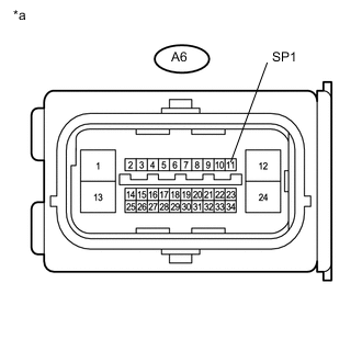
Text in Illustration *a Front view of wire harness connector
(to Brake Actuator Assembly [Skid Control ECU])
Measure the voltage according to the value(s) in the table below.
Standard Voltage Tester Connection Switch Condition Specified Condition A6-11 (SP1) - Body ground Ignition switch ON 11 to 14 V
-
NG
CHECK HARNESS AND CONNECTOR (COMBINATION METER ASSEMBLY - SKID CONTROL ECU) Click here
OK
-
-
CHECK COMBINATION METER ASSEMBLY (SPEED SIGNAL)
-
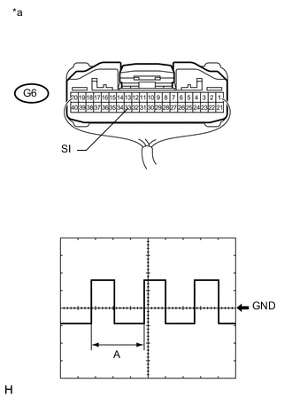
Text in Illustration *a Component with harness connected
(Combination Meter Assembly)
Check the input waveform.
-
Remove the combination meter assembly with the connector(s) still connected Click here.
-
Connect an oscilloscope to terminal G6-33 (SI) and body ground.
-
Turn the ignition switch to ON.
-
Check the signal waveform according to the condition(s) in the table below.
Measurement Condition Item Condition Terminal No. (Symbol) G6-33 (SI) - Body ground Tool setting 5 V/DIV., 20 ms./DIV. Condition Driving at approximately 20 km/h (12 mph) OK The waveform displayed is as shown in the illustration. Tech Tips
When the system is functioning normally, one wheel revolution generates 4 pulses. As the vehicle speed increases, the width indicated by A in the illustration narrows.
Result Result Proceed to OK A NG (for LHD, w/ Hydraulic Brake Booster) B NG (for RHD, w/ Hydraulic Brake Booster) C NG (w/ Vacuum Brake Booster) D
-
A 
REPLACE COMBINATION METER ASSEMBLY Click here
B
REPLACE MASTER CYLINDER SOLENOID (SKID CONTROL ECU) Click here
C
REPLACE MASTER CYLINDER SOLENOID (SKID CONTROL ECU) Click here
D
REPLACE BRAKE ACTUATOR ASSEMBLY (SKID CONTROL ECU) Click here
-
-
CHECK HARNESS AND CONNECTOR (COMBINATION METER ASSEMBLY - SKID CONTROL ECU)
-
for 1GR-FE, 1KD-FTV, 1GD-FTV:
-
Disconnect the G6 combination meter assembly connector.
-
Disconnect the A7 master cylinder solenoid (skid control ECU) connector.
-
Measure the resistance according to the value(s) in the table below.
Standard Resistance Tester Connection Condition Specified Condition G6-33 (SI) - A7-12 (SP1) Always Below 1 Ω A7-12 (SP1) - Body ground Always 10 kΩ or higher
-
-
for 2TR-FE, 5L-E:
-
Disconnect the G6 combination meter assembly connector.
-
Disconnect the A6 brake actuator assembly (skid control ECU) connector.
-
Measure the resistance according to the value(s) in the table below.
Standard Resistance Tester Connection Condition Specified Condition G6-33 (SI) - A6-11 (SP1) Always Below 1 Ω A6-11 (SP1) - Body ground Always 10 kΩ or higher
-
OK
REPLACE COMBINATION METER ASSEMBLY Click here
NG
REPAIR OR REPLACE HARNESS OR CONNECTOR
-
-
CHECK HARNESS AND CONNECTOR (COMBINATION METER ASSEMBLY - NO. 3 JUNCTION BLOCK)
-
Disconnect the G6 combination meter assembly connector.
-
Disconnect the 3A No. 3 junction block connector.
-
Measure the resistance according to the value(s) in the table below.
Standard Resistance Tester Connection Condition Specified Condition G6-32 (+S) - 3A-59 Always Below 1 Ω G6-32 (+S) - Body ground Always 10 kΩ or higher
NG
REPAIR OR REPLACE HARNESS OR CONNECTOR
OK
-
-
CHECK HARNESS AND CONNECTOR (NO. 3 JUNCTION BLOCK)
-
Inspect for a short in the circuit that is connected to the junction block connector shown in the wiring diagram.
Tech Tips
If the voltage is not as specified, it is possible that an ECU or circuit has a malfunction. The malfunctioning ECU or circuit will be diagnosed in the following steps.
-
Disconnect the No. 3 junction block connectors.
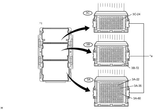
Text in Illustration *1 No. 3 Junction Block - - *a Front view of wire harness connector
(to No. 3 Junction Block)
- - -
Measure the voltage according to the value(s) in the table below.
Standard Voltage Tester Connection Condition Specified Condition 3C-24 - Body ground*1 Ignition switch ON 4.5 to 14 V 3B-72 - Body ground*2 Ignition switch ON 4.5 to 14 V 3A-22 - Body ground*3 Ignition switch ON 4.5 to 14 V 3A-60 - Body ground Ignition switch ON 4.5 to 14 V 3A-35 - Body ground*4 Ignition switch ON 4.5 to 14 V
-
*1: w/ Auto Wiper System
-
*2: w/ Entry and Start System
-
*3: w/ Audio and Visual System or Navigation System
-
*4: w/ Tire Pressure Monitor System
Result Result Proceed to Voltage is not as specified in one circuit A Voltage is as specified in all circuits B -
-
B
REPLACE NO. 3 JUNCTION BLOCK
A
-
-
SYSTEM CHECK
-
Select the circuit for which voltage was not as specified in the previous step.
Result Tester Connection System that Uses the Circuit Proceed to 3C-24 - Body ground Auto wiper system*1 A 3B-72 - Body ground Entry and start system*2 B 3A-22 - Body ground Audio and visual system*3 or navigation system*4 C 3A-60 - Body ground SFI system, TOYOTA parking assist-sensor system*5, automatic transmission system*6, *7 D 3A-35 - Body ground Tire pressure monitor system*8 E
-
*1: w/ Auto Wiper System
-
*2: w/ Entry and Start System
-
*3: w/ Audio and Visual System
-
*4: w/ Navigation System
-
*5: w/ TOYOTA Parking Assist-sensor System
-
*6: for 1KD-FTV
-
*7: for Automatic Transmission
-
*8: w/ Tire Pressure Monitor System
-
B
CHECK HARNESS AND CONNECTOR (NO. 3 JUNCTION BLOCK - POWER MANAGEMENT CONTROL ECU) Click here
C
CHECK HARNESS AND CONNECTOR (NO. 3 JUNCTION BLOCK - JUNCTION CONNECTOR) Click here
D
CHECK HARNESS AND CONNECTOR (NO. 3 JUNCTION BLOCK - NO. 4 JUNCTION BLOCK) Click here
E
CHECK HARNESS AND CONNECTOR (NO. 3 JUNCTION BLOCK - TIRE PRESSURE MONITOR RECEIVER ASSEMBLY) Click here
A
-
-
CHECK HARNESS AND CONNECTOR (NO. 3 JUNCTION BLOCK - WINDSHIELD WIPER SWITCH ASSEMBLY)
-
Disconnect the G120 auto wiper switch connector.
-
Measure the resistance according to the value(s) in the table below.
Standard Resistance Tester Connection Condition Specified Condition G120-6 (SPD) - Body ground*1, *2 Always 10 kΩ or higher G120-4 (SPD) - Body ground*3 Always 10 kΩ or higher
-
*1: for LHD
-
*2: for RHD, LH Side Type
-
*3: for RHD, RH Side Type
-
OK
REPLACE WINDSHIELD WIPER SWITCH ASSEMBLY Click here
NG
REPAIR OR REPLACE HARNESS OR CONNECTOR
-
-
CHECK HARNESS AND CONNECTOR (NO. 3 JUNCTION BLOCK - POWER MANAGEMENT CONTROL ECU)
-
Disconnect the G51 power management control ECU connector.
-
Measure the resistance according to the value(s) in the table below.
Standard Resistance Tester Connection Condition Specified Condition G51-23 (SPD) - Body ground Always 10 kΩ or higher
OK
REPLACE POWER MANAGEMENT CONTROL ECU Click here
NG
REPAIR OR REPLACE HARNESS OR CONNECTOR
-
-
CHECK HARNESS AND CONNECTOR (NO. 3 JUNCTION BLOCK - JUNCTION CONNECTOR)
-
Disconnect the 3A No. 3 junction block connector.
-
Disconnect the H24 junction connector.
-
Measure the resistance according to the value(s) in the table below.
Standard Resistance Tester Connection Condition Specified Condition 3A-22 - Body ground Always 10 kΩ or higher
NG
REPAIR OR REPLACE HARNESS OR CONNECTOR
OK
-
-
CHECK HARNESS AND CONNECTOR (JUNCTION CONNECTOR)
-
Inspect for a short in the circuit that is connected to the junction connector shown in the wiring diagram.
-
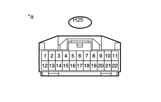
Text in Illustration *a Front view of wire harness connector
(Junction Connector)
Disconnect the junction connector.
-
Measure the voltage according to the value(s) in the table below
Standard Voltage Tester Connection Switch Condition Specified Condition H25-10 - Body ground*1 Ignition switch ON 4.5 to 14 V H25-11 - Body ground*2 Ignition switch ON 4.5 to 14 V
-
*1: w/ Audio and Visual System or Navigation System
-
*2: w/ Stereo Component Amplifier
Result Result Proceed to NG (H25-10 - Body ground) (w/ Audio and Visual System [for Radio Receiver Type]) A NG (H25-10 - Body ground) (w/ Audio and Visual System [for Radio and Display Type]) B NG (H25-10 - Body ground) (w/ Navigation System) C NG (H25-11 - Body ground) D OK E -
-
B
CHECK HARNESS AND CONNECTOR (JUNCTION CONNECTOR - RADIO AND DISPLAY RECEIVER ASSEMBLY) Click here
C
CHECK HARNESS AND CONNECTOR (JUNCTION CONNECTOR - NAVIGATION RECEIVER ASSEMBLY) Click here
D
CHECK HARNESS AND CONNECTOR (JUNCTION CONNECTOR - STEREO COMPONENT AMPLIFIER ASSEMBLY) Click here
E
REPLACE JUNCTION CONNECTOR
A
-
-
CHECK HARNESS AND CONNECTOR (JUNCTION CONNECTOR - RADIO RECEIVER ASSEMBLY)
-
Disconnect the H47 radio receiver assembly connector.
-
Measure the resistance according to the value(s) in the table below.
Standard Resistance Tester Connection Condition Specified Condition H47-17 (SPD) - Body ground Always 10 kΩ or higher
OK
REPLACE RADIO RECEIVER ASSEMBLY Click here
NG
REPAIR OR REPLACE HARNESS OR CONNECTOR
-
-
CHECK HARNESS AND CONNECTOR (JUNCTION CONNECTOR - RADIO AND DISPLAY RECEIVER ASSEMBLY)
-
Disconnect the H51 radio and display receiver assembly connector.
-
Measure the resistance according to the value(s) in the table below.
Standard Resistance Tester Connection Condition Specified Condition H51-17 (SPD) - Body ground Always 10 kΩ or higher
OK
REPLACE RADIO AND DISPLAY RECEIVER ASSEMBLY Click here
NG
REPAIR OR REPLACE HARNESS OR CONNECTOR
-
-
CHECK HARNESS AND CONNECTOR (JUNCTION CONNECTOR - NAVIGATION RECEIVER ASSEMBLY)
-
Disconnect the H56 navigation receiver assembly connector.
-
Measure the resistance according to the value(s) in the table below.
Standard Resistance Tester Connection Condition Specified Condition H56-17 (SPD) - Body ground Always 10 kΩ or higher
OK
REPLACE NAVIGATION RECEIVER ASSEMBLY Click here
NG
REPAIR OR REPLACE HARNESS OR CONNECTOR
-
-
CHECK HARNESS AND CONNECTOR (JUNCTION CONNECTOR - STEREO COMPONENT AMPLIFIER ASSEMBLY)
-
Disconnect the H63 stereo component amplifier assembly connector.
-
Measure the resistance according to the value(s) in the table below.
Standard Resistance Tester Connection Condition Specified Condition H63-11 (SPD) - Body ground Always 10 kΩ or higher
OK
REPLACE STEREO COMPONENT AMPLIFIER ASSEMBLY Click here
NG
REPAIR OR REPLACE HARNESS OR CONNECTOR
-
-
CHECK HARNESS AND CONNECTOR (NO. 3 JUNCTION BLOCK - NO. 4 JUNCTION BLOCK)
-
Disconnect the 3A No. 3 junction block connector.
-
Disconnect the 4A No. 4 junction block connector.
-
Measure the resistance according to the value(s) in the table below.
Standard Resistance Tester Connection Condition Specified Condition 3A-60 (+S) - 4A-48 Always Below 1 Ω 3A-60 (+S) - Body ground Always 10 kΩ or higher
NG
REPAIR OR REPLACE HARNESS OR CONNECTOR
OK
-
-
CHECK HARNESS AND CONNECTOR (NO. 4 JUNCTION BLOCK)
-
Inspect for a short in the circuit that is connected to the junction connector shown in the wiring diagram.
-
Disconnect the No. 4 junction block connectors.
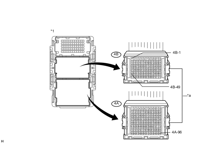
Text in Illustration *1 No. 4 Junction Block - - *a Front view of wire harness connector
(to No. 4 Junction Block)
- - -
Measure the voltage according to the value(s) in the table below
Standard Voltage Tester Connection Switch Condition Specified Condition 4B-49 - Body ground*1 Ignition switch ON 4.5 to 14 V 4B-1 - Body ground*2, *3 Ignition switch ON 4.5 to 14 V 4A-96 - Body ground Ignition switch ON 4.5 to 14 V
-
*1: w/ TOYOTA Parking Assist-sensor System
-
*2: for 1KD-FTV
-
*3: for Automatic Transmission
Result Result Proceed to NG (4B-49 - Body ground) A NG (4B-1 - Body ground) B NG (4A-96 - Body ground) C OK D -
-
B
CHECK HARNESS AND CONNECTOR (NO. 4 JUNCTION BLOCK - TCM) Click here
C
CHECK HARNESS AND CONNECTOR (NO. 4 JUNCTION BLOCK - ECM) Click here
D
REPLACE NO. 4 JUNCTION BLOCK
A
-
-
CHECK HARNESS AND CONNECTOR (NO. 4 JUNCTION BLOCK - CLEARANCE WARNING ECU)
-
Disconnect the I1 clearance warning ECU connector.
-
Measure the resistance according to the value(s) in the table below.
Standard Resistance Tester Connection Condition Specified Condition I1-3 (SPD) - Body ground Always 10 kΩ or higher Result Result Proceed to OK (for LHD) A OK (for RHD) B NG C
A
REPLACE CLEARANCE WARNING ECU ASSEMBLY Click here
B
REPLACE CLEARANCE WARNING ECU ASSEMBLY (for RHD) Click here
C
REPAIR OR REPLACE HARNESS OR CONNECTOR
-
-
CHECK HARNESS AND CONNECTOR (NO. 4 JUNCTION BLOCK - TCM)
-
Disconnect the G70 TCM connector.
-
Measure the resistance according to the value(s) in the table below.
Standard Resistance Tester Connection Condition Specified Condition G70-25 (SPD1) - Body ground Always 10 kΩ or higher
OK
REPLACE TCM Click here
NG
REPAIR OR REPLACE HARNESS OR CONNECTOR
-
-
CHECK HARNESS AND CONNECTOR (NO. 4 JUNCTION BLOCK - ECM)
-
Disconnect the G55*1, G56*2, G181*3, G58*4, G184*5 or G182*6 ECM connector.
-
*1: for 1GR-FE, Automatic Transmission
-
*2: for 1GR-FE, Manual Transmission
-
*3: for 2TR-FE
-
*4: for 1KD-FTV
-
*5: for 1GD-FTV
-
*6: for 5L-E
-
-
Measure the resistance according to the value(s) in the table below.
Standard Resistance for 1GR-FE, Automatic Transmission Tester Connection Condition Specified Condition G56-12 (SPD) - Body ground Always 10 kΩ or higher for 1GR-FE, Manual Transmission Tester Connection Condition Specified Condition G55-18 (SPD) - Body ground Always 10 kΩ or higher for 2TR-FE Tester Connection Condition Specified Condition G181-23 (SPD) - Body ground Always 10 kΩ or higher for 1KD-FTV Tester Connection Condition Specified Condition G58-30 (SPD) - Body ground Always 10 kΩ or higher for 1GD-FTV Tester Connection Condition Specified Condition G184-10 (SPD) - Body ground Always 10 kΩ or higher for 5L-E Tester Connection Condition Specified Condition G182-25 (SP1) - Body ground Always 10 kΩ or higher Tech Tips
-
for 1GR-FE:
If it is necessary to replace the ECM, refer to the following procedures Click here.
-
for 2TR-FE:
If it is necessary to replace the ECM, refer to the following procedures Click here.
-
for 1KD-FTV:
If it is necessary to replace the ECM, refer to the following procedures Click here.
-
for 1GD-FTV:
If it is necessary to replace the ECM, refer to the following procedures Click here.
-
for 5L-E:
If it is necessary to replace the ECM, refer to the following procedures Click here.
-
OK
REPLACE ECM
NG
REPAIR OR REPLACE HARNESS OR CONNECTOR
-
-
CHECK HARNESS AND CONNECTOR (NO. 3 JUNCTION BLOCK - TIRE PRESSURE MONITOR RECEIVER ASSEMBLY)
-
Disconnect the R41 tire pressure monitor receiver connector.
-
Measure the resistance according to the value(s) in the table below.
Standard Resistance Tester Connection Condition Specified Condition R41-2 (SPD) - Body ground Always 10 kΩ or higher
OK
REPLACE TIRE PRESSURE MONITOR RECEIVER ASSEMBLY Click here
NG
REPAIR OR REPLACE HARNESS OR CONNECTOR
-