ENGINE ASSEMBLY INSTALLATION
CAUTION / NOTICE / HINT
Tech Tips
Perform "Inspection After Repairs" after replacing the engine assembly, cylinder head sub-assembly, camshaft, No. 2 camshaft, camshaft timing gear assembly, camshaft timing exhaust gear assembly, piston sub-assembly or piston ring Click here.
PROCEDURE
-
INSTALL NO. 1 ENGINE HANGER
-
REMOVE ENGINE FROM ENGINE STAND
-
Attach an engine sling device and hang the engine assembly with a chain block.
Note
Pay attention to the angle of the sling device as the engine assembly or No. 1 engine hanger may be damaged or deformed if the angle is incorrect.
-
Lift the engine assembly and remove it from the engine stand.
-
-
INSTALL ENGINE ASSEMBLY
Tech Tips
Perform "Inspection After Repairs" after replacing the engine assembly Click here.
-
Slowly lower the engine assembly into the engine compartment.
-
Install the engine assembly with the 4 bolts and 4 nuts.
- Torque:
- 40 N*m { 408 kgf*cm, 30 ft.*lbf }
-
Remove the 2 bolts and 2 No. 1 engine hangers.
-
-
INSTALL REAR END PLATE
-
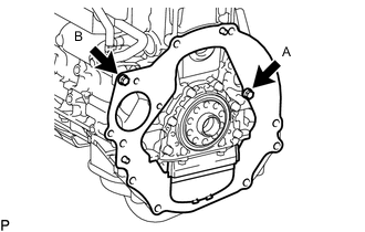
Install the rear end plate with the 2 bolts.
- Torque:
- for bolt A
- 18 N*m { 184 kgf*cm, 13 ft.*lbf }
- for bolt B
- 18 N*m { 178 kgf*cm, 13 ft.*lbf }
-
Attach the flywheel housing dust seal.
-
-
INSTALL FLYWHEEL SUB-ASSEMBLY (for Manual Transmission)
-
INSTALL CLUTCH DISC ASSEMBLY (for Manual Transmission)
-
INSTALL CLUTCH COVER ASSEMBLY (for Manual Transmission)
-
INSPECT AND ADJUST CLUTCH COVER ASSEMBLY (for Manual Transmission)
-
INSTALL DRIVE PLATE AND RING GEAR SUB-ASSEMBLY (for Automatic Transmission)
-
INSTALL REAR NO. 1 ENGINE MOUNTING INSULATOR
Tech Tips
Perform this procedure only when replacement of the rear No. 1 engine mounting insulator is necessary.
-
Install the rear No. 1 engine mounting insulator.
-
for Manual Transmission Click here
-
for Automatic Transmission Click here
-
-
-
INSTALL MANUAL TRANSMISSION ASSEMBLY (for Manual Transmission)
-
INSTALL AUTOMATIC TRANSMISSION ASSEMBLY (for Automatic Transmission)
-
INSTALL STARTER ASSEMBLY
-
for 1.4 kW Type: Click here
-
for 2.0 kW Type: Click here
-
-
INSTALL DRIVE PLATE AND TORQUE CONVERTER CLUTCH SETTING BOLT (for Automatic Transmission)
-
INSTALL FRONT PROPELLER SHAFT ASSEMBLY
-
INSTALL PROPELLER SHAFT ASSEMBLY
-
INSTALL FRONT EXHAUST PIPE ASSEMBLY
-
CONNECT ENGINE WIRE
-
Install the bracket to the engine mounting insulator LH with the bolt.
- Torque:
- 13 N*m { 131 kgf*cm, 9 ft.*lbf }
-
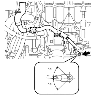
Text in Illustration *a 45° or less Install the ground wire and engine wire with the 2 clamps and bolt.
- Torque:
- 40 N*m { 408 kgf*cm, 30 ft.*lbf }
-
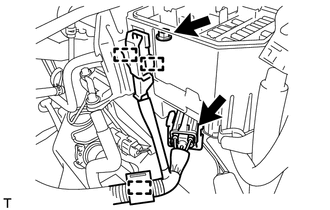
Attach the 2 clamps to connect the wire harness to the engine room No. 1 relay block.
-
Install the nut.
- Torque:
- 11 N*m { 112 kgf*cm, 8 ft.*lbf }
-
Connect the connector and attach the clamp.
-
Connect the ECM connector.
-
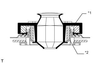
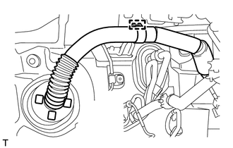
Attach the grommet to the wire harness support.
Text in Illustration *1 Grommet *2 Wire Harness Support -
Pass the wire harness into the vehicle and install the wire harness support.
-
Attach the clamp.
-
Connect the 9 connectors and attach the clamp.
-
Install the glove compartment door Click here.
-
-
Attach the 3 clamps and connect the engine wire to the vehicle RH side.
-
-
INSTALL FRONT NO. 1 FENDER APRON TO FRAME SEAL LH
-
INSTALL FRONT NO. 1 FENDER APRON TO FRAME SEAL RH
-
CONNECT COOLER COMPRESSOR ASSEMBLY
-
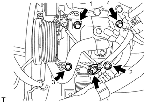
Temporarily install the cooler compressor assembly with the 4 bolts.
-
Tighten the bolts in the order shown in the illustration to connect the cooler compressor assembly.
- Torque:
- 25 N*m { 250 kgf*cm, 18 ft.*lbf }
-
Connect the connector.
-
Connect the suction hose with the bolt.
- Torque:
- 7.8 N*m { 80 kgf*cm, 69 in.*lbf }
-
-
CONNECT VANE PUMP ASSEMBLY
-
Connect the vane pump assembly with the 2 bolts.
- Torque:
- 21 N*m { 214 kgf*cm, 15 ft.*lbf }
-
Connect the 2 connectors.
-
Install the pressure feed tube with the bolt.
- Torque:
- 28 N*m { 285 kgf*cm, 21 ft.*lbf }
-
-
CONNECT HEATER HOSE
-
for Single Air Conditioning System:
Connect the 2 heater hoses to the heater core, and slide the 2 clips to secure the hoses.
-
for Dual Air Conditioning System:
Connect the 2 heater hoses to the water by-pass pipe and hose, and slide the 2 clips to secure the hoses.
-
-
CONNECT UNION TO CHECK VALVE HOSE
-
Connect the union to check valve hose to the brake booster assembly, and slide the clip to secure the hose.
-
-
CONNECT PURGE LINE HOSE
-
Connect the purge line hose to the purge VSV, and slide the clip to secure the hose.
-
-
INSTALL NO. 2 FUEL HOSE
-
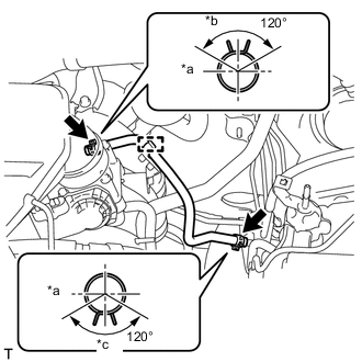
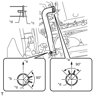
Text in Illustration *a Front *b Top *c LH Side Install the No. 2 fuel hose to the fuel pressure regulator and floor pipe, and slide the clip to secure the hose.
Tech Tips
The direction of each clip is indicated in the illustration.
-
Attach the clamp.
-
-
INSTALL FUEL HOSE
-
Install the fuel hose Click here.
-
Attach the 2 clamps.
-
-
CONNECT NO. 1 OIL COOLER INLET HOSE AND NO. 1 OIL COOLER OUTLET HOSE (for Automatic Transmission)
-
INSTALL FAN SHROUD
-
INSTALL NO. 2 RADIATOR HOSE
-
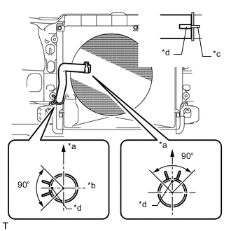
Text in Illustration *a Top *b RH Side *c Protrusion *d Paint Mark Install the No. 2 radiator hose so that its paint marks align with the radiator assembly and water inlet protrusion as shown in the illustration and slide the 2 clips to secure the hose.
Tech Tips
The direction of each clip is indicated in the illustration.
-
-
INSTALL NO. 1 RADIATOR HOSE
-
Text in Illustration *a Top *b LH Side *c Protrusion *d Paint Mark Install the No. 1 radiator hose so that its paint marks align with the radiator assembly and cylinder head protrusions as shown in the illustration and slide the 2 clips to secure the hose.
Tech Tips
The direction of each clip is indicated in the illustration.
-
-
INSTALL RADIATOR RESERVOIR
-
INSTALL NO. 1 AIR INJECTION SYSTEM HOSE
-
Install the No. 1 air injection system hose to the air switching valve assembly and air pump assembly, and slide the 2 clips to secure the hose.
-
Install a new hose clamp.
-
-
INSTALL INTAKE AIR CONNECTOR
-
INSTALL AIR CLEANER CASE
-
Install the air cleaner case with the 3 bolts.
- Torque:
- 12 N*m { 122 kgf*cm, 9 ft.*lbf }
-
Install the air cleaner filter element sub-assembly.
-
-
INSTALL AIR CLEANER CAP SUB-ASSEMBLY
-
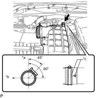
Text in Illustration *a Upper Side *b Front *c Matchmark Install the air cleaner hose and align its matchmark with the matchmark of the intake air connector as shown in the illustration.
-
Tighten the hose clamp.
Note
Check that the air cleaner hose is securely installed.
-
Attach the 4 clamps.
-
Connect the mass air flow meter connector and attach the 3 clamps.
-
-
INSTALL COWL TOP VENTILATOR LOUVER SUB-ASSEMBLY
-
INSTALL HOOD SUB-ASSEMBLY
-
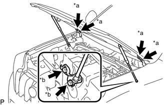
Text in Illustration *a Bolt A *b Bolt B Install the hood sub-assembly with the 8 bolts.
- Torque:
- for bolt A
- 13 N*m { 133 kgf*cm, 10 ft.*lbf }
- for bolt B
- 18 N*m { 184 kgf*cm, 13 ft.*lbf }
-
Connect the washer nozzle hose.
-
-
ADJUST HOOD SUB-ASSEMBLY
-
CONNECT CABLE TO NEGATIVE BATTERY TERMINAL
Note
When disconnecting the cable, some systems need to be initialized after the cable is reconnected Click here.
-
ADD AUTOMATIC TRANSMISSION FLUID (for Automatic Transmission)
-
ADD ENGINE OIL
-
ADD ENGINE COOLANT
-
INSPECT SHIFT LEVER POSITION
-
INSPECT FOR OIL LEAK
-
INSPECT ENGINE OIL LEVEL
-
INSPECT FOR COOLANT LEAK
-
INSPECT FOR FUEL LEAK
-
INSPECT FOR EXHAUST GAS LEAK
-
INSPECT IGNITION TIMING
-
INSPECT ENGINE IDLE SPEED
-
INSPECT CO/HC
-
INSTALL UPPER RADIATOR SUPPORT SEAL
-
Install the upper radiator support seal with the 13 clips.
-
-
INSTALL REAR ENGINE UNDER COVER ASSEMBLY
-
Install the rear engine under cover with the 4 bolts.
- Torque:
- 29 N*m { 296 kgf*cm, 21 ft.*lbf }
-
-
INSTALL TRANSMISSION UNDER COVER
-
Install the transmission under cover with the 2 bolts.
- Torque:
- 29 N*m { 296 kgf*cm, 21 ft.*lbf }
-
-
INSTALL NO. 1 ENGINE UNDER COVER SUB-ASSEMBLY
-
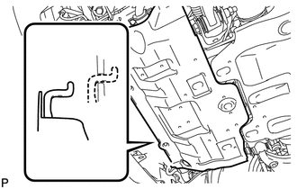
Hook the No. 1 engine under cover sub-assembly to the vehicle body as shown in the illustration.
-
Install the 4 bolts.
- Torque:
- 29 N*m { 296 kgf*cm, 21 ft.*lbf }
-
-
INSTALL FRONT BUMPER COVER LOWER
-
Install the front bumper cover lower with the 5 bolts and clip.
- Torque:
- 8.0 N*m { 82 kgf*cm, 71 in.*lbf }
-
-
INSPECT ENGINE COOLANT LEVEL