ENGINE ASSEMBLY REMOVAL
PROCEDURE
-
PRECAUTION
Note
After turning the ignition switch off, waiting time may be required before disconnecting the cable from the battery terminal. Therefore, make sure to read the disconnecting the cable from the battery terminal notice before proceeding with work Click here.
-
DISCHARGE FUEL SYSTEM PRESSURE
-
DISCONNECT CABLE FROM NEGATIVE BATTERY TERMINAL
Note
When disconnecting the cable, some systems need to be initialized after the cable is reconnected Click here.
-
REMOVE HOOD SUB-ASSEMBLY
-
Disconnect the washer nozzle hose.
-
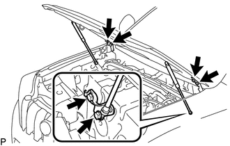
Remove the 8 bolts and hood sub-assembly.
Note
If the hood support is detached from the ball joint, it become non-reusable. Therefore, do not detach the hood support from the ball joint unless replacing it.
-
-
REMOVE COWL TOP VENTILATOR LOUVER SUB-ASSEMBLY
-
REMOVE FRONT BUMPER COVER LOWER
-
Remove the clip, 5 bolts and front bumper cover lower.
-
-
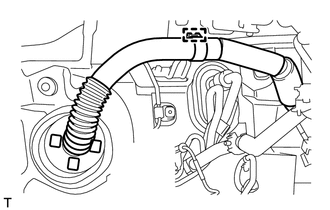
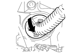
REMOVE NO. 1 ENGINE UNDER COVER SUB-ASSEMBLY
-
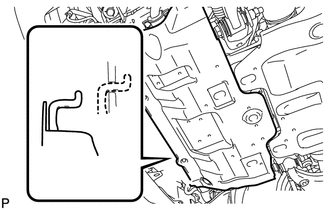
Remove the 4 bolts.
-
Unhook the No. 1 engine under cover sub-assembly from the vehicle body as shown in the illustration.
-
-
REMOVE TRANSMISSION UNDER COVER
-
Remove the 2 bolts and transmission under cover.
-
-
REMOVE REAR ENGINE UNDER COVER ASSEMBLY
-
Remove the 4 bolts and rear engine under cover assembly.
-
-
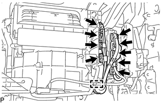
REMOVE UPPER RADIATOR SUPPORT SEAL
-
Remove the 13 clips and upper radiator support seal.
-
-
DRAIN ENGINE COOLANT
-
DRAIN ENGINE OIL
-
DRAIN AUTOMATIC TRANSMISSION FLUID (for Automatic Transmission)
-
REMOVE AIR CLEANER CAP SUB-ASSEMBLY
-
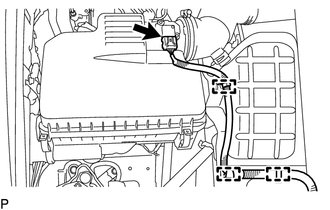
Detach the 3 clamps and disconnect the mass air flow meter connector.
-
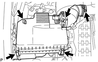
Detach the 4 clamps.
-
Loosen the hose clamp and remove the air cleaner cap sub-assembly.
-
-
REMOVE AIR CLEANER CASE
-
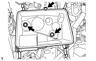
Remove the air cleaner filter element sub-assembly.
-
Remove the 3 bolts and air cleaner case.
-
-
REMOVE INTAKE AIR CONNECTOR
-
REMOVE NO. 1 AIR INJECTION SYSTEM HOSE
-
Remove the hose clamp.
Note
Do not reuse the hose clamp.
-
Slide the 2 clips and remove the No. 1 air injection system hose from the air switching valve assembly and air pump assembly.
-
-
REMOVE RADIATOR RESERVOIR
-
REMOVE NO. 1 RADIATOR HOSE
-
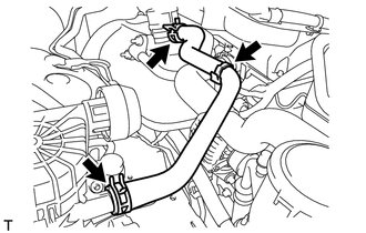
Slide the 2 clips and remove the No. 1 radiator hose from the radiator assembly and cylinder head sub-assembly.
-
-
REMOVE NO. 2 RADIATOR HOSE
-
Slide the 2 clips and remove the No. 2 radiator hose from the radiator assembly and water inlet.
-
-
REMOVE FAN SHROUD
-
REMOVE NO. 1 OIL COOLER INLET HOSE AND NO. 1 OIL COOLER OUTLET HOSE (for Automatic Transmission)
-
REMOVE FUEL HOSE
-
Detach the 2 clamps.
-
Remove the fuel hose Click here.
-
-
REMOVE NO. 2 FUEL HOSE
-
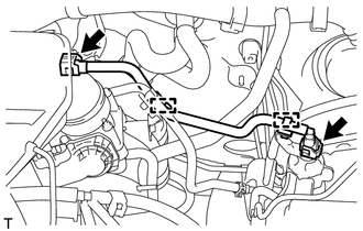
Detach the clamp.
-
Slide the 2 clips and remove the No. 2 fuel hose from the fuel pressure regulator and floor pipe.
-
-
DISCONNECT PURGE LINE HOSE
-
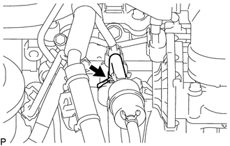
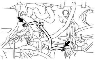
Slide the clip and disconnect the purge line hose from the purge VSV.
-
-
DISCONNECT UNION TO CHECK VALVE HOSE
-
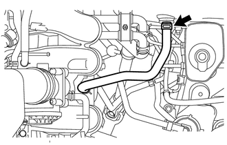
Slide the clip and disconnect the union to check valve hose from the brake booster assembly.
-
-
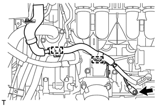
DISCONNECT HEATER HOSE
-
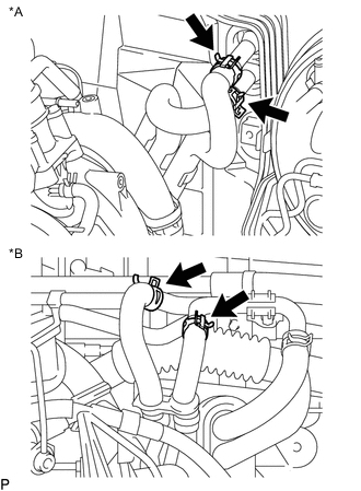
Text in Illustration *A for Single Air Conditioning System *B for Dual Air Conditioning System for Single Air Conditioning System:
Slide the 2 clips and disconnect the 2 heater hoses from the heater core.
-
for Dual Air Conditioning System:
Slide the 2 clips and disconnect the 2 heater hoses from the water by-pass pipe and hose.
-
-
DISCONNECT VANE PUMP ASSEMBLY
-
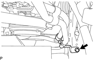
Remove the bolt and disconnect the pressure feed tube.
-
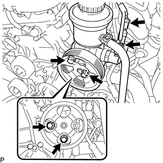
Disconnect the 2 connectors.
-
Remove the 2 bolts and disconnect the vane pump assembly.
Tech Tips
It is not necessary to completely remove the vane pump assembly. With the hoses connected to the vane pump assembly, hang the vane pump assembly on the vehicle body with a rope.
-
-
DISCONNECT COOLER COMPRESSOR ASSEMBLY
-
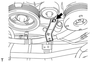
Remove the bolt and disconnect the suction hose from the engine.
-
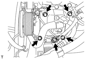
Disconnect the connector.
-
Remove the 4 bolts and disconnect the cooler compressor assembly.
Tech Tips
It is not necessary to completely remove the cooler compressor assembly. With the hoses connected to the cooler compressor assembly, hang the cooler compressor assembly on the vehicle body with a rope.
-
-
REMOVE FRONT NO. 1 FENDER APRON TO FRAME SEAL RH
-
REMOVE FRONT NO. 1 FENDER APRON TO FRAME SEAL LH
-
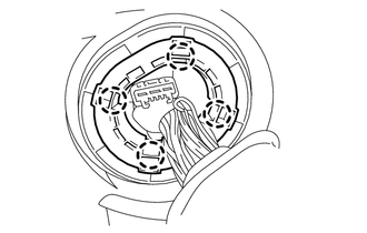
DISCONNECT ENGINE WIRE
-
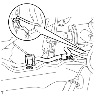
Detach the 3 clamps and disconnect the engine wire from the vehicle RH side.
-
Disconnect the ECM connector.
-
Remove the glove compartment door Click here.
-
Detach the clamp and disconnect the 9 connectors.
-
Detach the clamp.
-
Detach the grommet from the wire harness support.
-
Detach the 4 claws to remove the wire harness support from the vehicle, and then pull out the ECM connector to remove it from the vehicle.
-
-
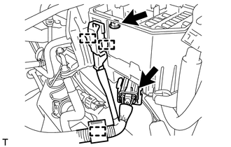
Disconnect the connector and detach the clamp.
-
Remove the nut from the engine room No. 1 relay block.
-
Detach the 2 clamps and disconnect the wire harness from the engine room No. 1 relay block.
-
Detach the 2 clamps.
-
Remove the bolt and disconnect the ground wire.
-
Remove the bolt and bracket from the engine mounting bracket LH.
-
-
REMOVE FRONT EXHAUST PIPE ASSEMBLY
-
REMOVE MANIFOLD STAY
-
REMOVE PROPELLER SHAFT ASSEMBLY
-
REMOVE FRONT PROPELLER SHAFT ASSEMBLY
-
REMOVE DRIVE PLATE AND TORQUE CONVERTER CLUTCH SETTING BOLT (for Automatic Transmission)
-
REMOVE STARTER ASSEMBLY
-
for 1.4 kW Type: Click here
-
for 2.0 kW Type: Click here
-
-
REMOVE AUTOMATIC TRANSMISSION ASSEMBLY (for Automatic Transmission)
-
REMOVE MANUAL TRANSMISSION ASSEMBLY (for Manual Transmission)
-
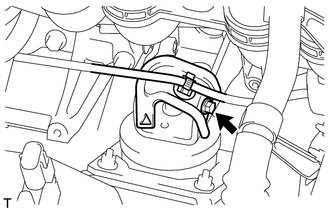
REMOVE REAR NO. 1 ENGINE MOUNTING INSULATOR
Tech Tips
Perform this procedure only when replacement of the engine mounting insulator is necessary.
-
Remove the rear No. 1 engine mounting insulator.
-
for Automatic Transmission Click here
-
for Manual Transmission Click here
-
-
-
REMOVE DRIVE PLATE AND RING GEAR SUB-ASSEMBLY (for Automatic Transmission)
-
REMOVE CLUTCH COVER ASSEMBLY (for Manual Transmission)
-
REMOVE CLUTCH DISC ASSEMBLY (for Manual Transmission)
-
REMOVE FLYWHEEL SUB-ASSEMBLY (for Manual Transmission)
-
REMOVE REAR END PLATE
-
Detach the flywheel housing dust seal.
-
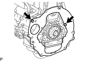
Remove the 2 bolts and rear end plate.
-
-
INSTALL NO. 1 ENGINE HANGER
-
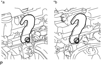
Text in Illustration *a LH Side *b RH Side Install 2 No. 1 engine hangers with 2 bolts as shown in the illustration.
- Torque:
- 42 N*m { 428 kgf*cm, 31 ft.*lbf }
Tech Tips
No. 1 Engine Hanger 12281-75050 Bolt 91672-81025
-
-
REMOVE ENGINE ASSEMBLY
-
Attach an engine sling device and hang the engine assembly with a chain block.
Note
Pay attention to the angle of the sling device as the engine assembly or engine hanger may be damaged or deformed if the angle is incorrect.
-
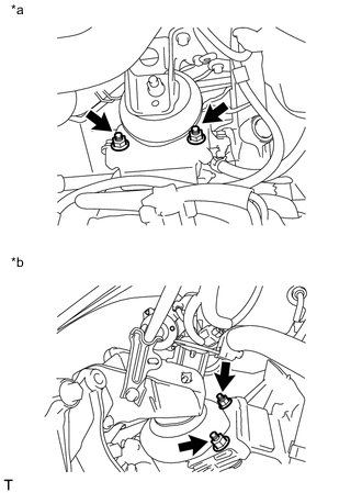
Text in Illustration *a RH Side *b LH Side Remove the 4 bolts and 4 nuts.
-
Lift the engine assembly out from the vehicle slowly and carefully.
Note
Make sure the engine assembly is clear of all wiring, hoses and cables.
-
-
INSTALL ENGINE TO ENGINE STAND
-
Install the engine assembly to an engine stand with bolts.
Note
-
Pay attention to the angle of the sling device as the engine assembly or engine hangers may be damaged or deformed if the angle is incorrect.
-
With the exception of installing the engine assembly to an engine stand or removing the engine assembly from an engine stand, do not perform any work on the engine while it is suspended, as doing so is dangerous.
-
-
Remove the 2 bolts and 2 No. 1 engine hangers.
-